
Disposable scalpel with retractable blade

a scalpel and retractable technology, applied in the field of scalpels, can solve the problems of two-part construction of the handle, the slider projecting through the side wall of the handle, and the number of the handle that cannot be easily used by a right-handed person,

Active Publication Date: 2008-01-01
MILTON TREVOR JOHN
View PDF11 Cites 311 Cited by
  • Summary
  • Abstract
  • Description
  • Claims
  • Application Information

AI Technical Summary

Benefits of technology

"The invention is a scalpel with a handle and a blade carrier that can be extended or retracted. The scalpel has a slider that can be snapped onto the blade carrier to hold it in place. The slider and the blade carrier have tooth and notch formations that releasably hold the blade carrier in place. The blade carrier can be locked in place by pressing a catch on the handle. The slider can have transverse tongues that lock into sockets in the blade carrier. The blade carrier can be used with different types of blades. The invention makes the scalpel easier to use and more versatile."

Problems solved by technology

The first type of scalpel that has the slider projecting through a side wall of the handle is considered to suffer from a number of disadvantages, not least of which is that one designed for use by a right-handed person cannot easily be used by a left-handed person and vice versa.
The second type of scalpel that has the slider projecting through the top edge of the scalpel handle generally has the disadvantage that the scalpel handle is made in two parts that are subsequently secured together with the blade carrier inside the handle and the associated slider projecting through a slot in the top edge of the composite handle.
The two-part construction of the handle is considered by applicant to be undesirable for a variety of reasons not least of which is the fact that the handle could possibly come apart.

Method used


Image

  • Disposable scalpel with retractable blade
  • Disposable scalpel with retractable blade
  • Disposable scalpel with retractable blade

Examples


Embodiment Construction

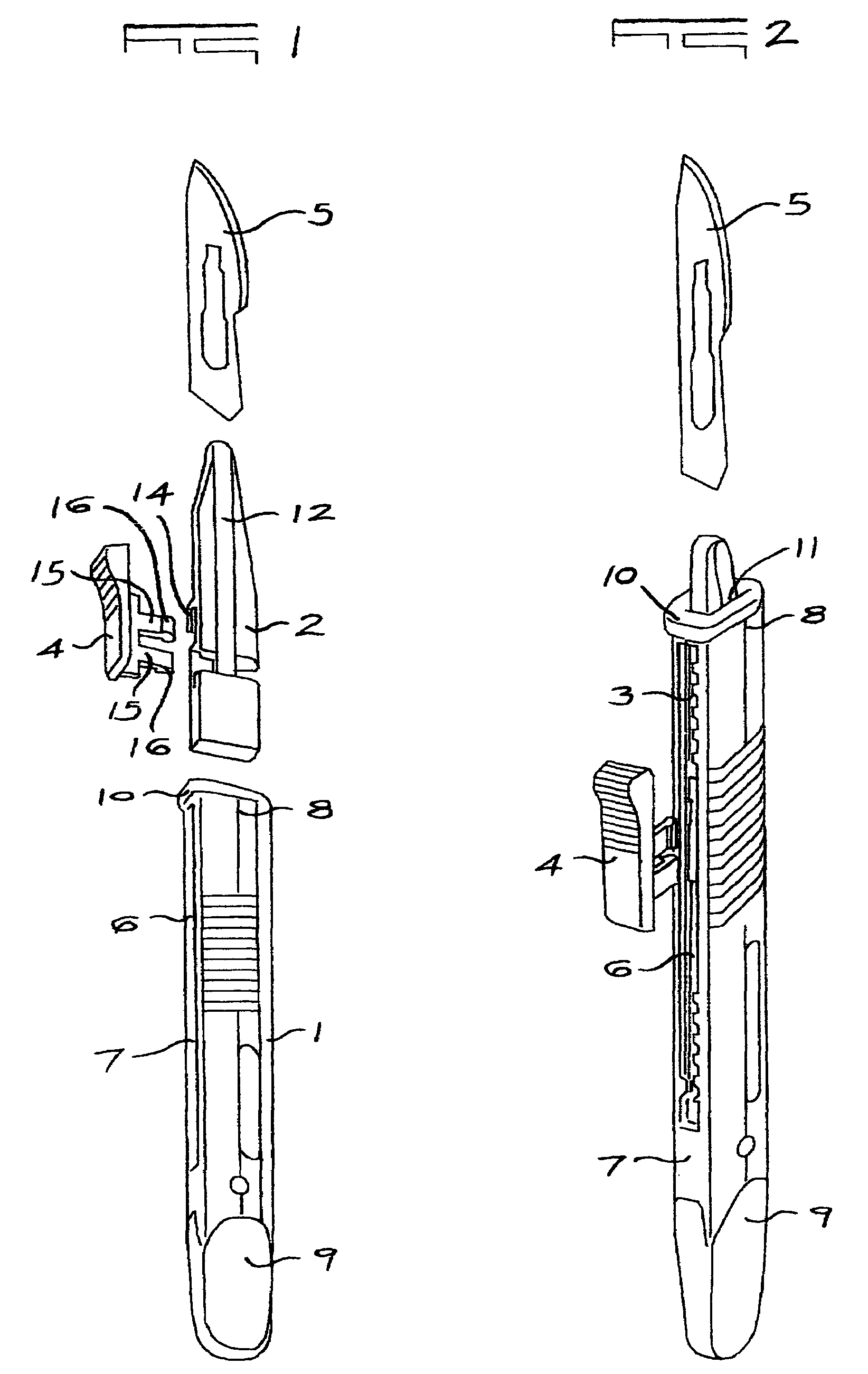
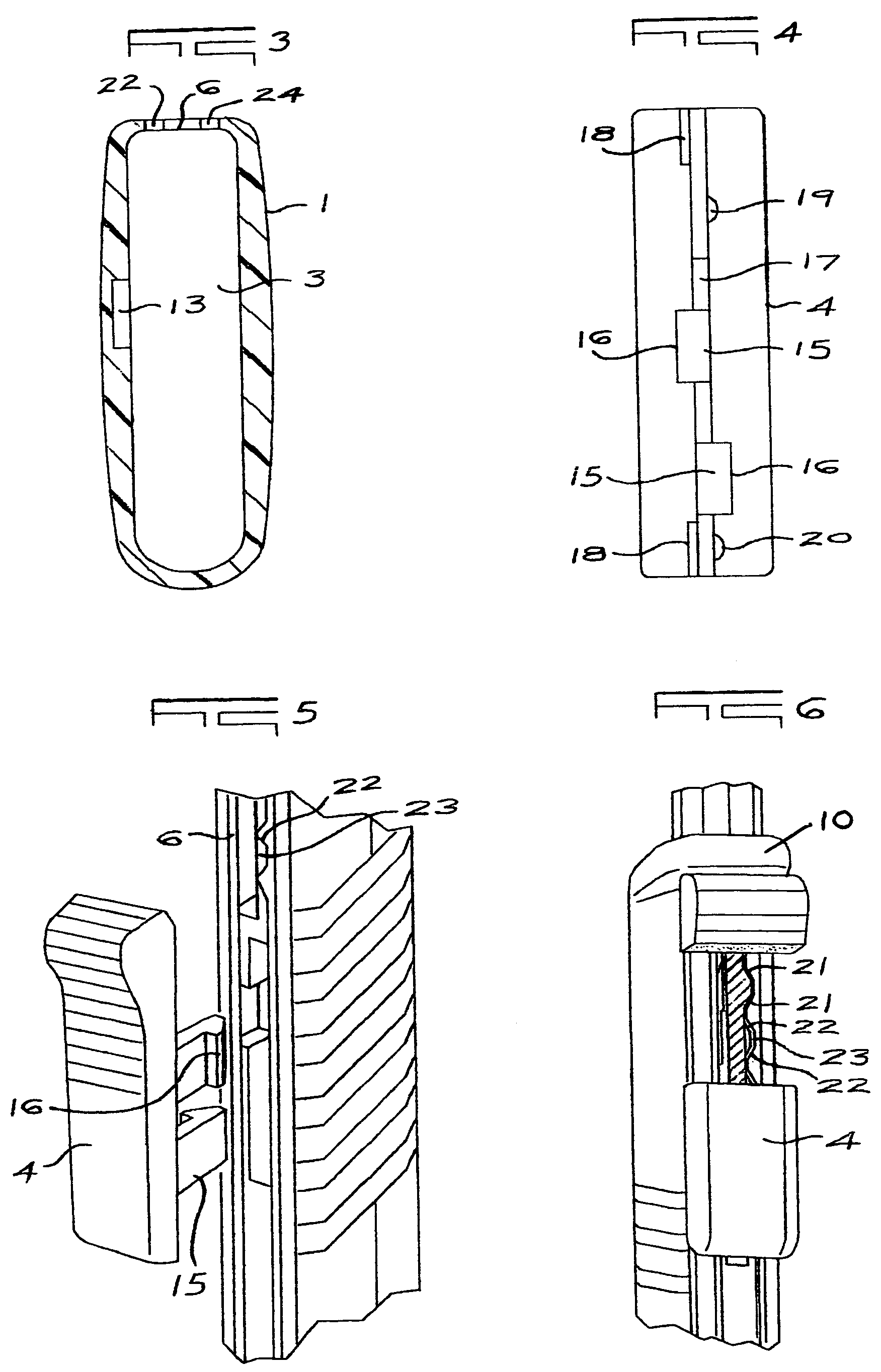
[0027]In the embodiment of the invention illustrated in FIGS. 1 to 9 of the drawings, a scalpel comprises a single piece injection moulded plastics handle (1), a blade carrier (2) slidable longitudinally in a longitudinal cavity (3) within the plastics handle, a separately moulded, manually operable slider (4) that combines with the blade carrier to form a blade carrier assembly in the assembled condition, and, for use, a scalpel blade (5) that is fitted to the blade carrier.

[0028]The handle has a longitudinally extending slot (6) extending along its operatively top edge (7) from a forward end (8) of the handle towards a rear end (9) thereof and communicating with the cavity inside. An integral bridge (10) at the front end of the top edge forms an endless collar to an open end (11) to the cavity and provides dimensional stability to this end for firmly holding the blade carrier in its operative position.

[0029]The blade carrier is elongate and has a longitudinally extending ridge (12...


PUM


Abstract

A scalpel is provided having a handle with a longitudinally extending cavity therein, a blade carrier within the cavity and movable longitudinally relative to the handle between an operative position in which a blade carried thereby is exposed for use at an open end of the cavity and an inoperative position in which a blade carried thereby is retracted within the cavity in the handle, and a manually operable slider associated with the blade carrier and passing through a slot in a wall of the handle at an edge thereof, herein termed the top edge. The handle is moulded as a single piece moulding with an integral bridge defining an endless open end to the cavity through which the blade carrier is introduced into the cavity. The slider is formed as a separate part that snap fits to the blade carrier after its introduction through the open end of the cavity to form a blade carrier and slider assembly. “Click stops” are provided in the operative and inoperative positions by tooth and notch formations on the slider and slot. A final innermost permanently locked position is also preferably provided.

Description

RELATED APPLICATIONS[0001]This application is a continuation-in-part application of U.S. application Ser. No. 10 / 657,023 filed Sep. 5, 2003 now abandoned that is abandoned in favour of this application.FIELD OF THE INVENTION[0002]This invention relates to a disposable scalpel having a retractable blade and, more particularly, to a disposable scalpel in which movement of the blade relative to a supporting scalpel handle between an extended operative position and a retracted inoperative position is achieved by moving a blade carrier by way of a thumb operable slider attached, generally by way of a slot through the wall of the handle, to the blade carrier.BACKGROUND TO THE INVENTION[0003]Disposable scalpels having retractable blades have been proposed and produced in many different forms. The various different forms can, for present purposes, be considered to fall into two different categories; a first being scalpels in which the thumb operable slider projects through a side wall of th...

Claims


Application Information

Patent Timeline
Patent Type & Authority Patents(United States)
IPC IPC(8): A61B17/32A61B17/00
CPCA61B17/3213A61B17/3217A61B2017/00451A61B2017/32113
Inventor HOLMAN, ROBERT GERARD
Owner MILTON TREVOR JOHN
Learn More