Rotating fore grip for small arms

a small arms and fore grip technology, applied in the field of firearms, can solve the problems of reducing the area of the warfighter's body to return fire, reducing the control of the trigger actuation and the recoil of the firearm, and the inability of conventional firearms to effectively fire at the target from behind the corner or obstacle without exposing a substantial portion of the warfighter's body

Inactive Publication Date: 2008-01-29
ARMY US SEC THE
View PDF7 Cites 23 Cited by
  • Summary
  • Abstract
  • Description
  • Claims
  • Application Information

AI Technical Summary

Problems solved by technology

While imaging devices, such as scopes and the like, are flexible enough to be used to generate a suitable image of the target regardless of line of sight, a conventional firearm lacks an ability to be effectively fired at the target from behind the corner or obstacle without exposing a substantial portion of the warfighter's body to return fire.
While this solution reduces the area of the warfighter's body to return fire, it has several disadvantages including that of reduced control over actuation of the trigger and over the recoil of the firearm.

Method used


Image

  • Rotating fore grip for small arms
  • Rotating fore grip for small arms
  • Rotating fore grip for small arms

Examples


Embodiment Construction

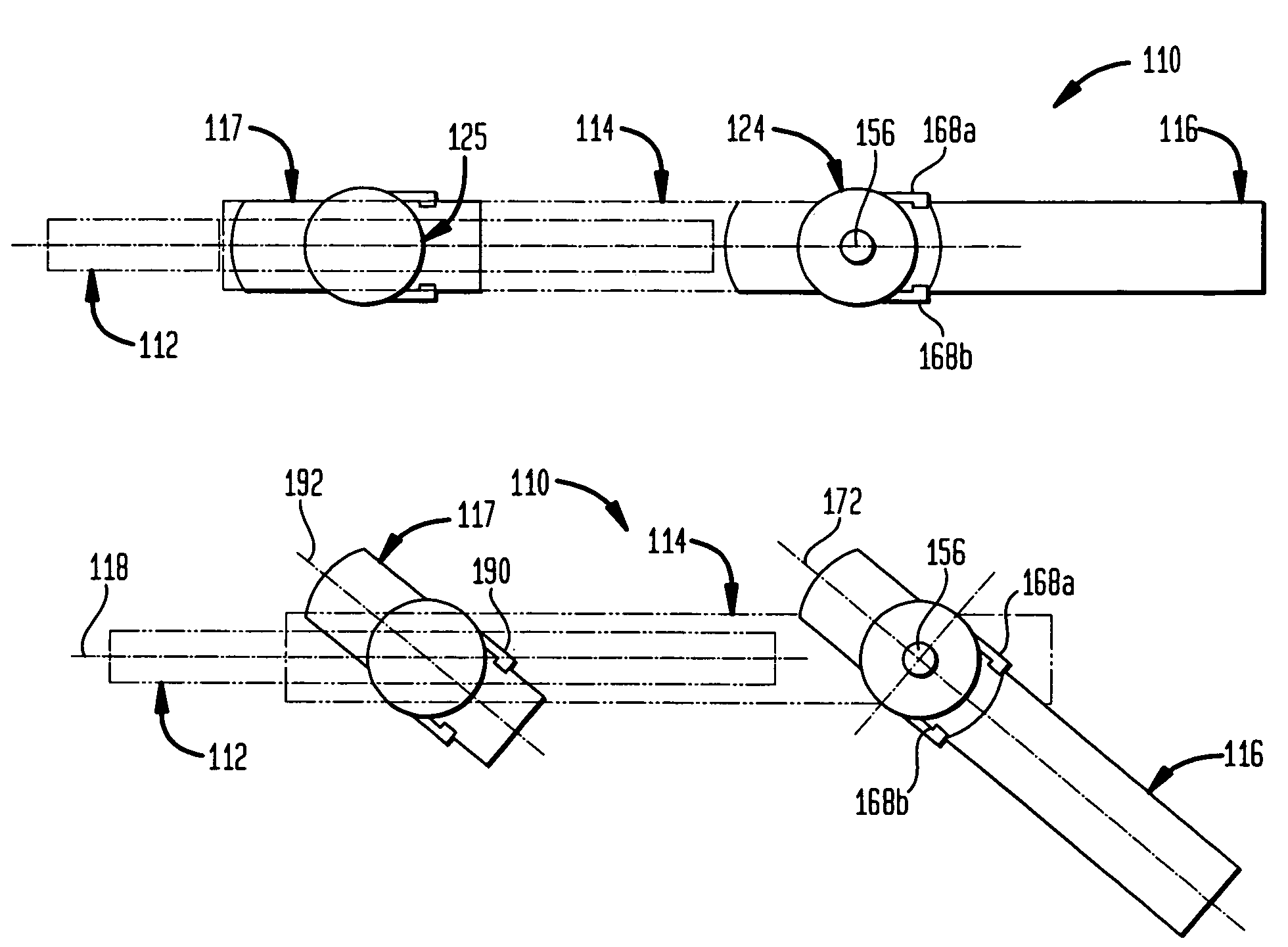
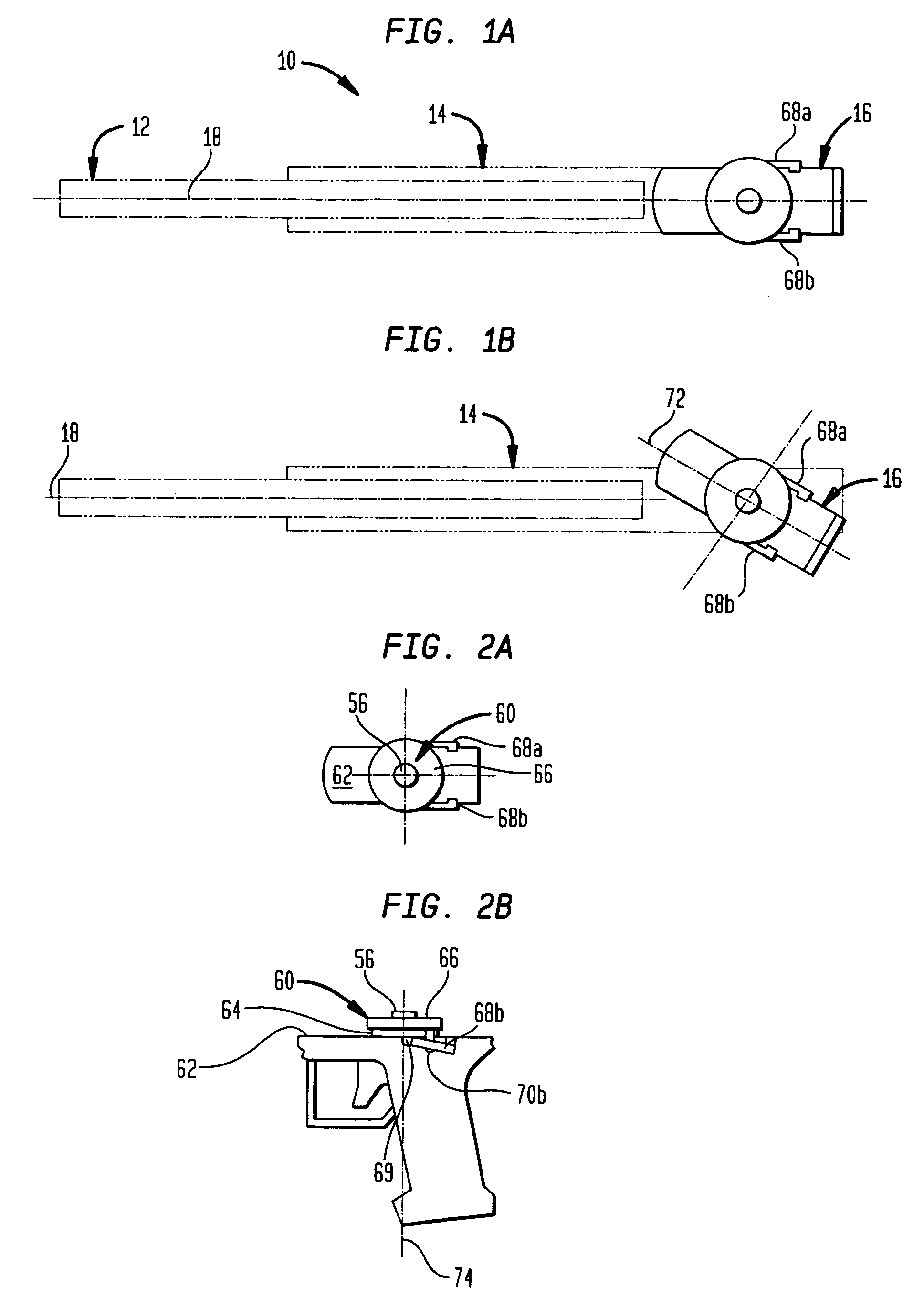
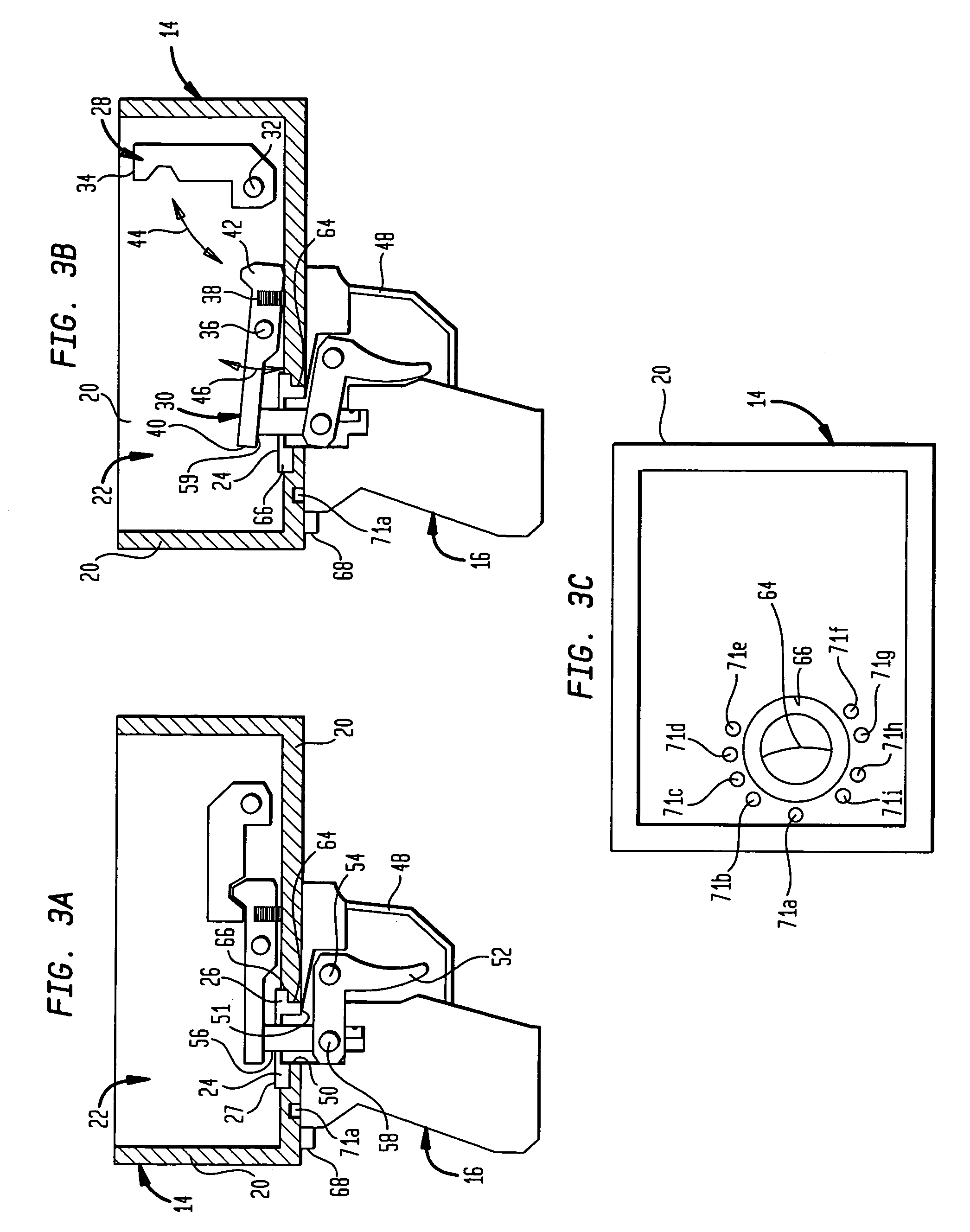
[0021]One embodiment of the present invention concerns a firearm which is configured to fire at a target from behind a corner or an obstacle without exposing a warfighter's body to return fire. More particularly, the firearm is configured such that it may be discharged along an axis at a relatively large angle to its conventional discharge axis, without requiring the warfighter who discharges the firearm, to be contorted while manipulating a trigger. In one particular embodiment, a fore grip and a gunstock including a trigger assembly may also be pivotal relative to the receiver thereof.

[0022]Referring now to FIGS. 1(a) and 1(b), a firearm, in accordance with one embodiment of the present invention, is illustrated generally at 10. In this embodiment, the firearm 10 comprises a barrel 12, a receiver 14 and a gunstock 16. The barrel 12 may be machined in a known manner from a suitably strong and durable material such as steel. The barrel 12 may be integrally connected to the receiver ...


PUM


Abstract

A firearm includes a barrel that has a central axis, a receiver fixedly supporting the barrel, a gunstock that is connected to the receiver and that has a longitudinal axis and a fore grip connected to the receiver. The gunstock and the receiver are each configured to provide for angular movement of the gunstock relative to the receiver and, in turn, the barrel and wherein the fore grip and the receiver are each configured to provide for angular movement of the fore grip relative to the receiver and, in turn, the barrel whereby the central axis of the barrel varies in a generally radial direction extending from the longitudinal axis of the gunstock. In this way, the firearm may be discharged by a warfighter, standing adjacent to a corner, around the corner.

Description

CROSS REFERENCE TO RELATED APPLICATION[0001]This application is a Continuation-In-Part of U.S. patent application Ser. No. 11 / 288,064, entitled “Rotating Hand Grip Trigger Assembly For Small Arms”, filed on Nov. 23, 2005 now abandoned, by the same inventor. This Continuation-In-Part is being filed under 37 CFR. § 1.53 and priority from the Nov. 23, 2005 effective date of the Parent Case (Ser. No. 11 / 288,064) is hereby claimed.GOVERNMENT INTEREST[0002]The invention described herein may be manufactured, used, imported, sold, and licensed by or for the Government of the United States of America without the payment of any royalty thereon or there for.BACKGROUND OF THE INVENTION[0003]1. Field of the Invention[0004]The present invention relates generally to firearms and, more particularly, to guns for use in urban combat.[0005]2. Related Art[0006]During urban warfare, many times a warfighter may be faced with a situation in which, in taking a position for cover, the warfighter may be loca...

Claims


Application Information

Patent Timeline
Patent Type & Authority Patents(United States)
IPC IPC(8): F41A11/04F41A21/00
CPCF41C23/04F41C23/16
Inventor LEUNG, FEE CHAN
Owner ARMY US SEC THE
Why Eureka
Try Eureka