Industrial robot

a robot and industrial technology, applied in the field of industrial robots, can solve the problems of limited wrist operation, worn out, and interference of the cable b>53/b> with the peripheral apparatus,

Active Publication Date: 2008-01-29
YASKAWA DENKI KK
View PDF15 Cites 24 Cited by
  • Summary
  • Abstract
  • Description
  • Claims
  • Application Information

AI Technical Summary

Benefits of technology

[0007]Therefore, it is an object of the invention to provide an industrial robot having no interference of a cable for an end effector or the like with a peripheral apparatus.

Problems solved by technology

Therefore, there is a problem in that the cable 53 interferes with a peripheral apparatus or the like.
Moreover, there is a problem in that the cable 53 is rubbed with the peripheral apparatus or the like and is thus worn out.
Furthermore, there is also a problem in that the operation of the wrist portion 58 is limited if the looseness of the cable is decreased to avoid the interference with the peripheral apparatus or the like.
Therefore, another problem is that the interference of the cable with the peripheral apparatus cannot be checked in the simulation such as by offline teaching.

Method used


Image

  • Industrial robot
  • Industrial robot
  • Industrial robot

Examples


Embodiment Construction

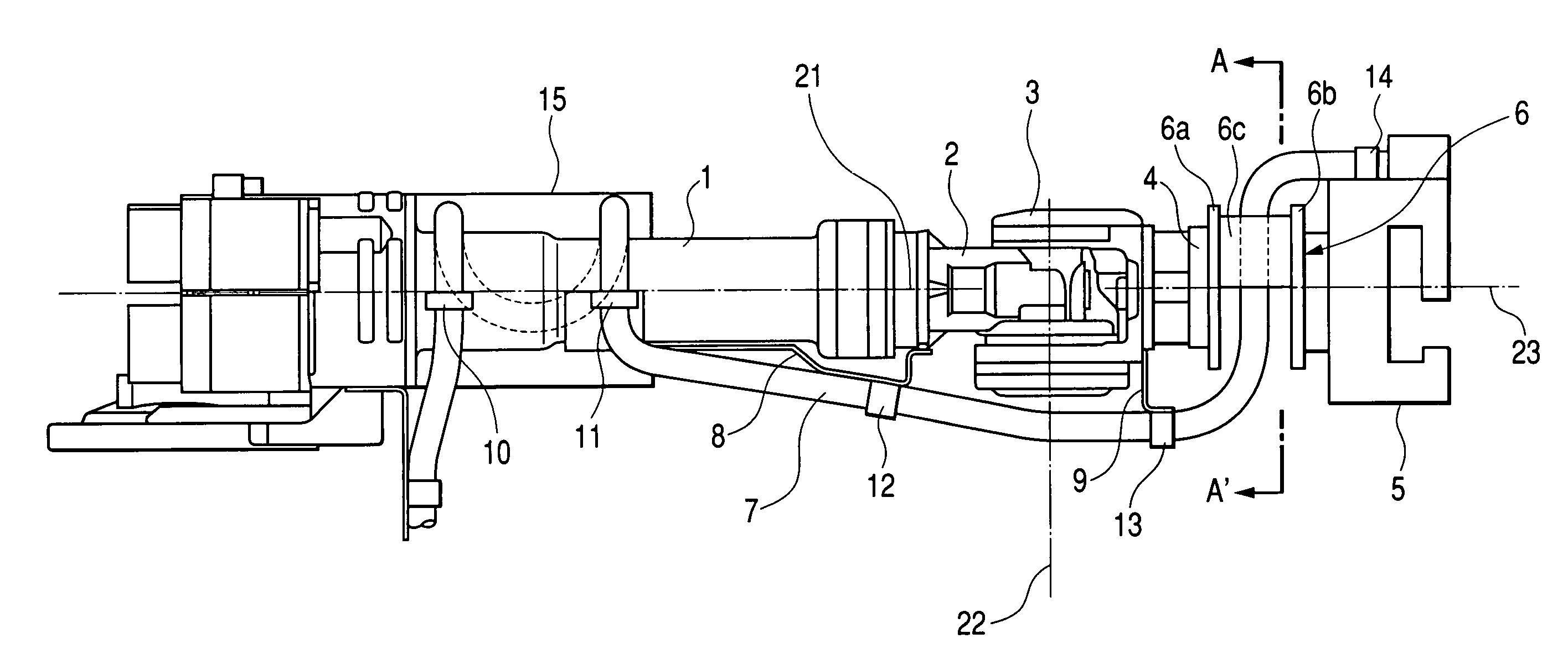
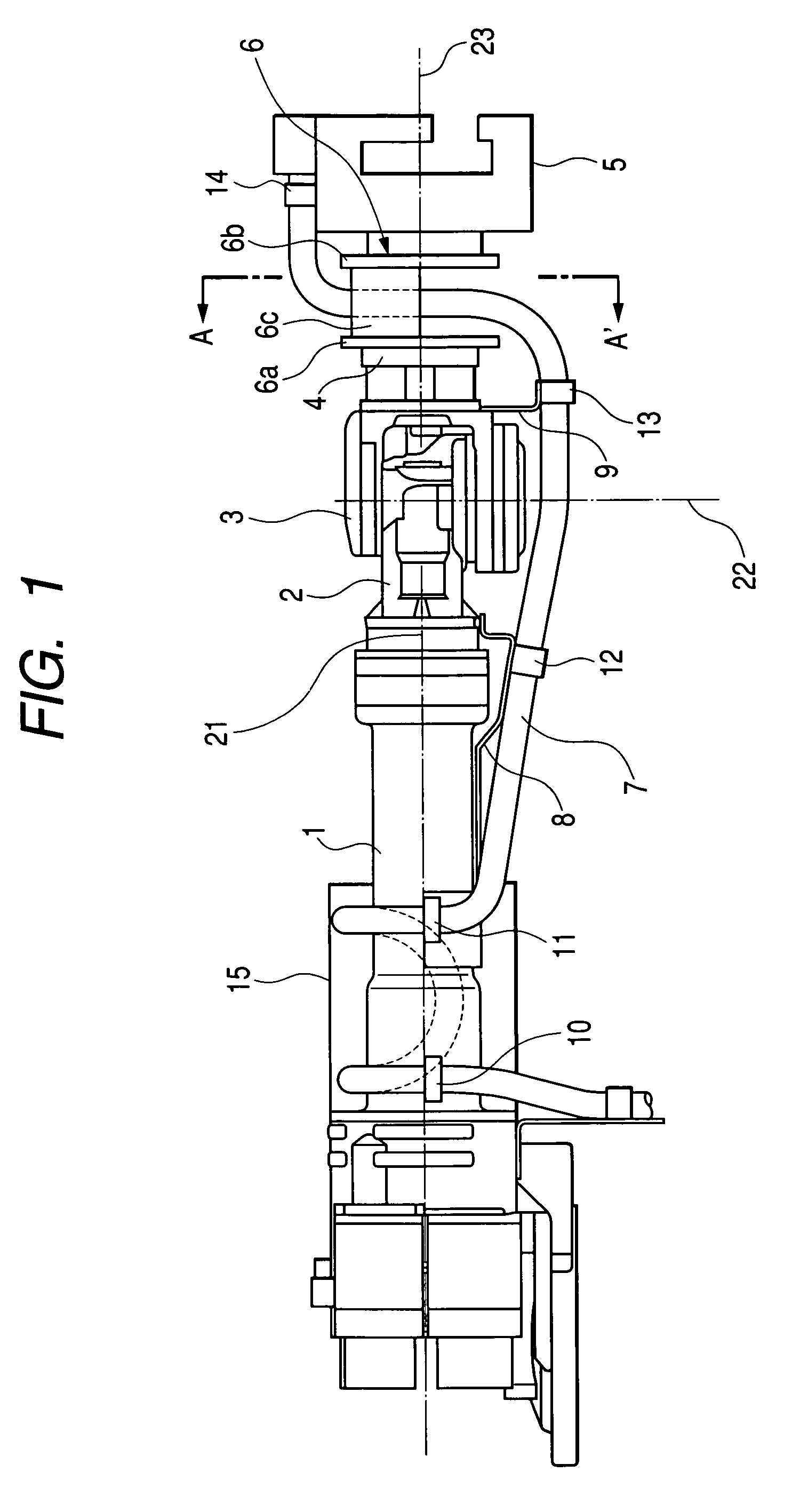
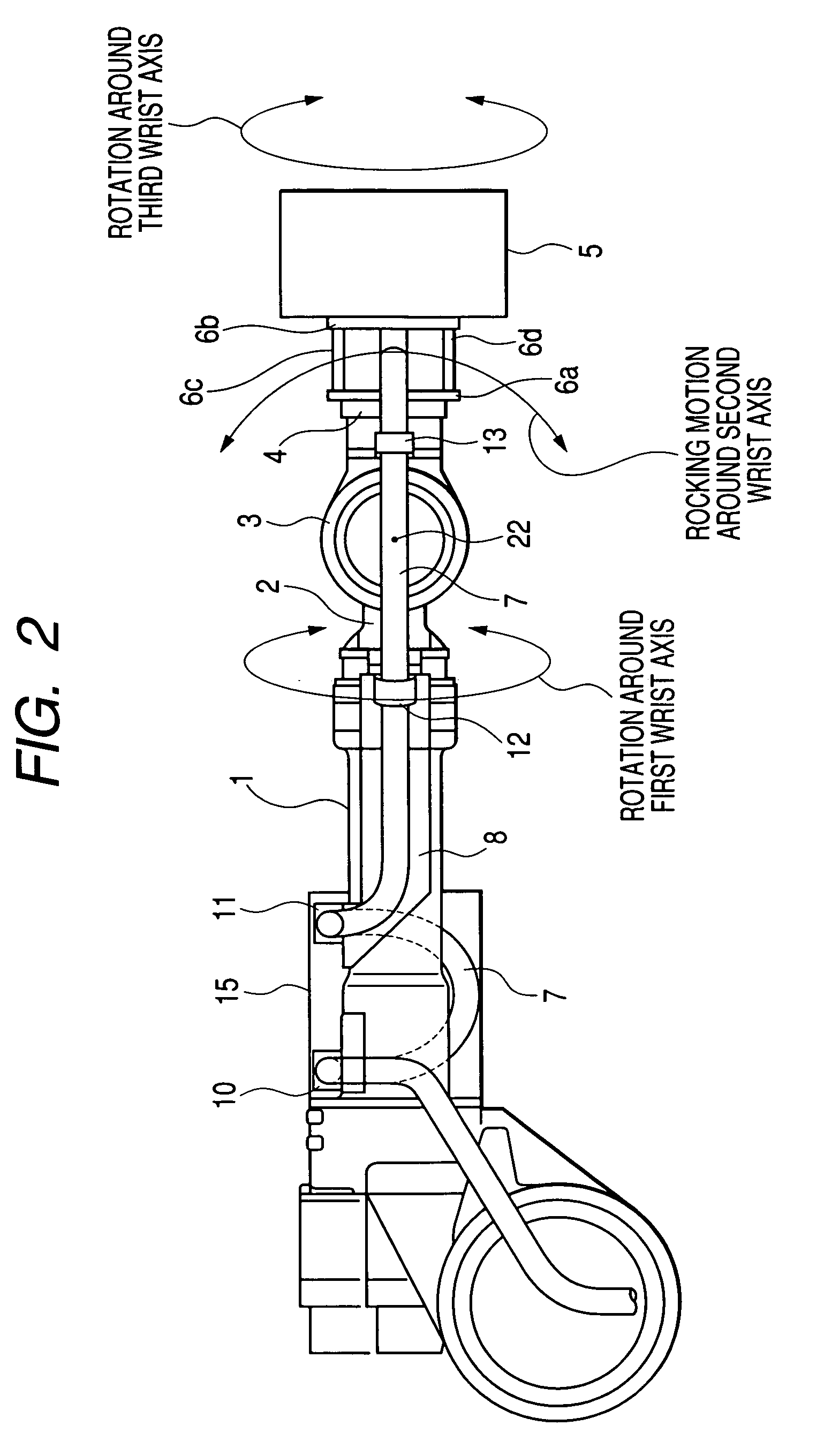
[0014]An embodiment of the invention will be described below with reference to the drawings. FIG. 1 is a plan view showing the upper arm of an industrial robot according to the embodiment of the invention and FIG. 2 is a side view showing the same, a part of which is shown in a section for convenience of explanation.

[0015]In the drawing, 1 denotes the upper arm of a so-called 6-axis vertical articulated robot. The tip of the upper arm 1 includes a wrist portion having a wrist base portion 2 to be rotated around a first wrist axis 21 in the longitudinal direction of the upper arm 1, a wrist rocking member 3 to be rocked around a second wrist axis 22 which is orthogonal to the first wrist axis, and a wrist flange 4 to be rotated around a third wrist axis 23 which is orthogonal to the second wrist axis 22.

[0016]5 denotes a spot welding gun which is an end effector fixed to the wrist flange 4 through an intermediate member 6. The intermediate member 6 is constituted by a first flange 6a...


PUM

PropertyMeasurementUnit
poweraaaaaaaaaa
degree of freedomaaaaaaaaaa
structureaaaaaaaaaa

Abstract

There is provided an industrial robot having no interference of a cable for an end effector or the like with a peripheral apparatus.An end effector 5 is fixed to a wrist flange 4 through an intermediate member 6. The intermediate member 6 takes the shape of a crankshaft in which a first flange 6a attached directly to the wrist flange 4, a second flange 6b provided at a predetermined interval in parallel with the first flange 6a and attached directly to the end effector 5, and two members 6c and 6d for coupling the first and second flanges 6a and 6b are arranged symmetrically.

Description

TECHNICAL FIELD[0001]The present invention relates to an industrial robot and more particularly to a vertical articulated robot for spot welding.BACKGROUND ART[0002]FIG. 4 is a side view showing a conventional spot welding robot. In FIG. 4, 51 denotes a 6-axis vertical articulated robot, 52 denotes a spot welding gun attached to the tip of the vertical articulated robot 51, and 53 denotes a cable for supplying a welding current to the spot welding gun.[0003]The vertical articulated robot 51 includes a fixing portion 54, a turning portion 55 supported pivotally on the fixing portion 54 and turned around a vertical axis, a lower arm 56 supported pivotally on the turning portion 55 and rocked in a longitudinal direction, an upper arm 57 supported pivotally on the lower arm 56 and rocked in a vertical direction, and a wrist portion 58 attached to the tip of the upper arm 57. The wrist portion 58 has the degree of freedom of a rotation around three axes which are orthogonal to each other...

Claims


Application Information

Patent Timeline
Patent Type & Authority Patents(United States)
IPC IPC(8): B25J17/00B25J17/02B25J18/00B23K11/11B23K11/24B25J19/00
CPCB25J19/0025Y10T74/20311Y10T74/20329
Inventor SHIRAKI, TOMOYUKIOKAHISA, MANABUYONEHARA, KEISUKEHANIYA, KAZUHIRO
Owner YASKAWA DENKI KK
Why Eureka
Try Eureka