Decorative light and landscape lighting system

a lighting system and decorative light technology, applied in outdoor lighting, decorative arts, edging using tiles, etc., can solve problems such as deterioration of the aesthetic value of edging

Inactive Publication Date: 2008-01-29
SNAPEDGE CANADA
View PDF17 Cites 56 Cited by
  • Summary
  • Abstract
  • Description
  • Claims
  • Application Information

AI Technical Summary

Problems solved by technology

Edging having a large plastic tubular top visible above the ground may deteriorate from the aesthetic value of the edging.

Method used


Image

  • Decorative light and landscape lighting system
  • Decorative light and landscape lighting system
  • Decorative light and landscape lighting system

Examples


Embodiment Construction

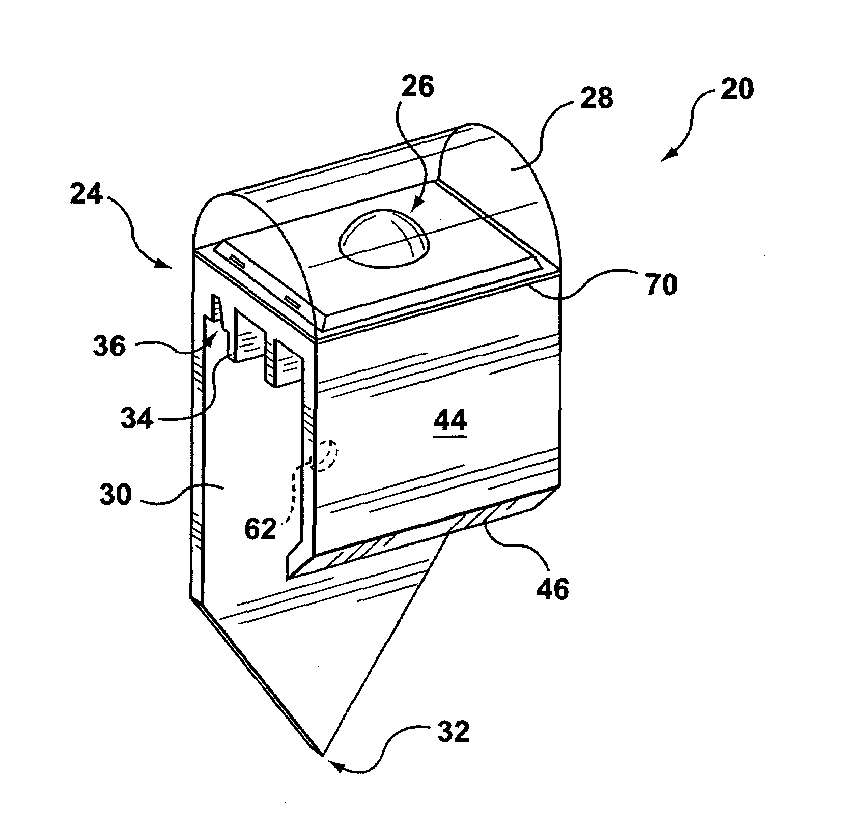
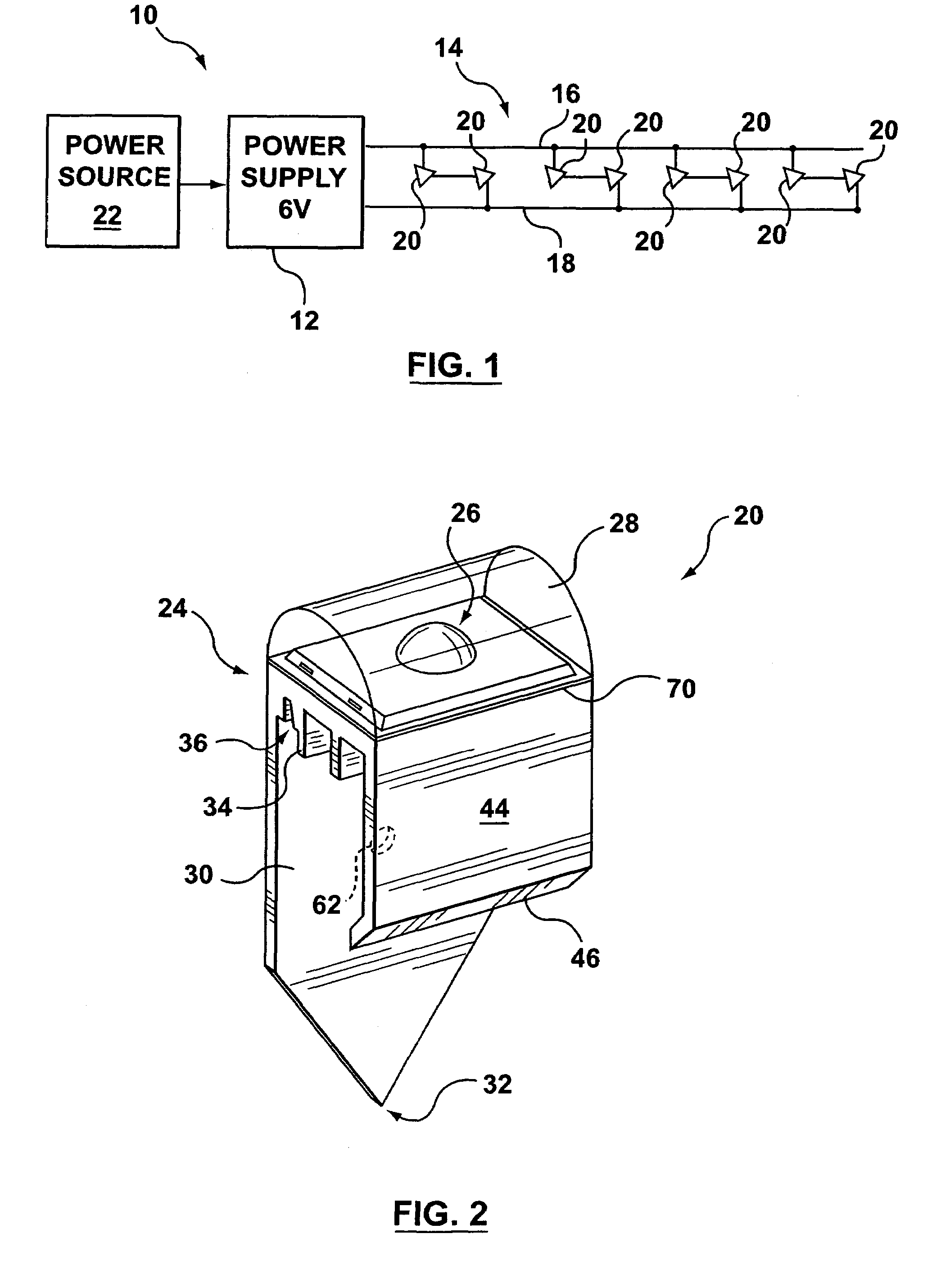
[0017]Reference is first made to FIG. 1, which shows a block diagram of an embodiment of a landscape lighting system 10.

[0018]The landscape lighting system 10 includes a low-voltage power supply 12 and a decorative lighting string 14. The decorative lighting string 14 includes a supply wire 16, a return wire 18, and decorative lights 20.

[0019]The decorative lights 20 may be connected in parallel, serial, or a combination thereof. In one embodiment, as shown in FIG. 1, the decorative lights 20 are connected in pairs serially with each pair then being connected in parallel with the other pairs. In this embodiment, the decorative lights 20 are electrically coupled to the supply wire 16 and return wire 18 at fixed locations. In another embodiment, the decorative lights 20 may include a clip-type electrical connector (not shown) for detachably connecting the decorative lights 20 to the lighting string 14 at desired locations. The clip-type electrical connector is designed to pierce an in...


PUM


Abstract

A decorative light and a landscape lighting system incorporating a plurality of decorative lights. The decorative lights are structured for attachment to the top of landscape edging. The lights include a body having a channel formed in its bottom surface for receiving the top edge of landscape edging. The channel may be formed by first and second downwardly projecting walls. The surface of the walls may provide an interior profile or key shape that corresponds to the shape of the top of the landscape edging. An illumination device, such as a light emitting diode, is housed within the decorative light.

Description

FIELD OF THE APPLICATION[0001]The present application relates to decorative lighting and, in particular, to a decorative light and a landscape lighting system.BACKGROUND INFORMATION[0002]There are many existing light strings designed to attach to gutters and trees for decorative purposes. Often, the light strings are intended for seasonal decorations. They are typically intended to be temporarily clipped to eavestroughs and then removed following the seasonal event.[0003]U.S. Pat. No. 5,410,458 to Bell proposes a light string incorporated into landscape edging. In particular, the Bell reference suggests a landscape edging having a tubular top edge of sufficient size to contain a string of miniature Christmas lights. The tubular top edge is substantially transparent, so as to allow for the emission of light. In order to use Bell's system, a user is required to replace existing landscape edging with Bell's edging that features a large tubular top. Edging having a large plastic tubular...

Claims


Application Information

Patent Timeline
Patent Type & Authority Patents(United States)
IPC IPC(8): F21V33/00A01G9/28
CPCA01G1/08F21V21/0824F21V21/088F21S9/02F21V31/005F21W2121/00F21W2131/109F21Y2101/02A01G9/28F21Y2115/10
Inventor BARNETT, DOUGLAS JOHNRENON, ATTILIO
Owner SNAPEDGE CANADA
Why Eureka
Try Eureka