Eye tracking method based on correlation and detected eye movement

a tracking method and eye tracking technology, applied in the field of eye tracking methods, can solve the problems of poor performance under real-world imaging conditions and the tendency of eye template accuracy to degenera

Active Publication Date: 2008-02-19
APTIV TECH LTD
View PDF15 Cites 34 Cited by
  • Summary
  • Abstract
  • Description
  • Claims
  • Application Information

AI Technical Summary

Problems solved by technology

While eye location and tracking algorithms can work reasonably well in a controlled environment, they tend to perform poorly under real world imaging conditions, particularly in systems having only one camera.
While this technique is useful, the accuracy of the eye template tends to degenerate over time due to drift and conditions such as out-of-plane rotation of the subject's head, noise and changes in the eye appearance (due to glasses, for example).

Method used


Image

  • Eye tracking method based on correlation and detected eye movement
  • Eye tracking method based on correlation and detected eye movement
  • Eye tracking method based on correlation and detected eye movement

Examples


Embodiment Construction

[0011]The eye tracking method of the present invention is disclosed in the context of a system that monitors a driver of a motor vehicle. However, it will be recognized that the method of this invention is equally applicable to other vision systems, whether vehicular or non-vehicular.

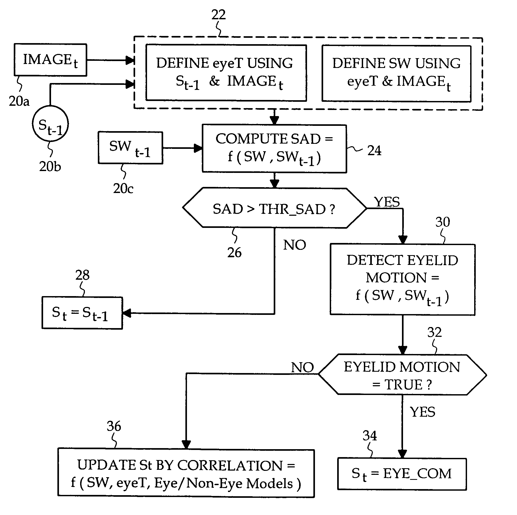
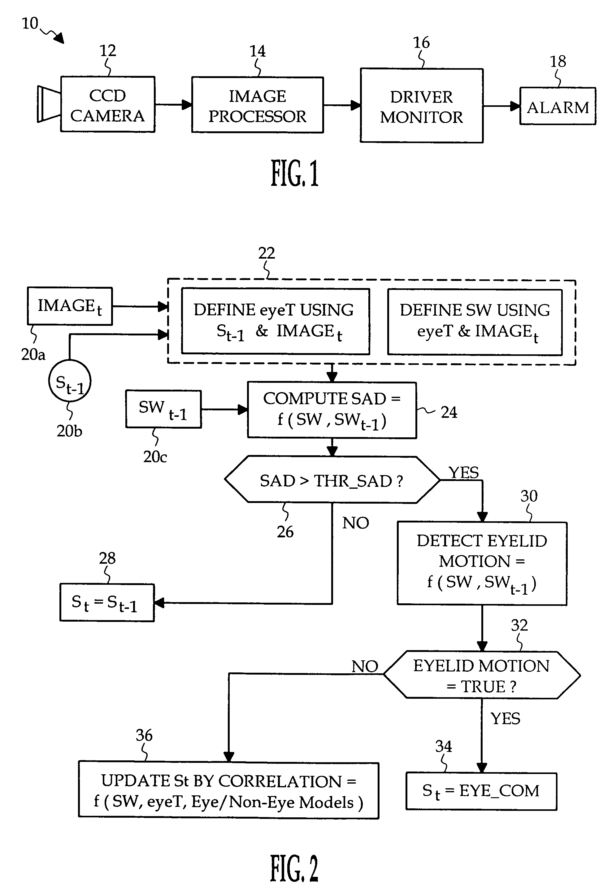
[0012]Referring to the drawings, and particularly to FIG. 1, the reference numeral 10 generally designates a motor vehicle vision system for monitoring driver alertness. The system 10 includes a CCD camera 12, a microprocessor-based image processor 14, a driver monitor 16, and an alarm 18. The camera 12 is mounted in a convenient location within the vehicle passenger compartment, such as in a center console or instrument panel, and is configured to produce an unobstructed image of the driver's head, taking into account differences in driver height and orientation. The image processor 14 captures a stream of video frames or images (IMAGEt-1, IMAGEt, etc.) produced by camera 12, and executes software rout...


PUM


Abstract

An eye tracking method tracks a subject's eye template by correlation between successive video frames, and periodically updates the eye template based on detected characteristic eye or eyelid movement such as blinking, eyelash movement and iris movement. In the absence of eyelid motion detection, a state vector corresponding to the center of the subject's eye is determined by a correlation technique, and when eyelid motion is detected, the state vector is determined based on the location of the detected motion.

Description

TECHNICAL FIELD[0001]The present invention relates to an eye tracking method that determines the location a subject's eye in a video image by correlation, and more particularly to a method of periodically updating the determined eye location based on detected characteristic eye movement.BACKGROUND OF THE INVENTION[0002]Vision systems frequently entail locating and tracking a subject's eye in an image generated by a video camera. In the motor vehicle environment, for example, a camera can be used to generate an image of the driver's face, and portions of the image corresponding to the driver's eyes can be analyzed to assess drive gaze or drowsiness. See, for example, the U.S. Pat. Nos. 5,795,306; 5,878,156; 5,926,251; 6,097,295; 6,130,617; 6,243,015; 6,304,187; and 6,571,002, incorporated herein by reference. While eye location and tracking algorithms can work reasonably well in a controlled environment, they tend to perform poorly under real world imaging conditions, particularly in...

Claims


Application Information

Patent Timeline
Patent Type & Authority Patents(United States)
IPC IPC(8): A61B3/14A61B3/00G06K9/00G06T7/20
CPCG06K9/00604G06T7/204G06T2207/10016G06T2207/30196G06T7/248G06V40/19
Inventor HAMMOUD, RIAD I.
Owner APTIV TECH LTD
Why Eureka
Try Eureka