

Seal for a gas turbine engine having improved flexibility
a gas turbine engine and flexible technology, applied in the field of flexible seals, can solve the problems of minimal flexibility of seals and overly rigid seals, and achieve the effect of reducing stresses along the weld joint region
- Summary
- Abstract
- Description
- Claims
- Application Information
AI Technical Summary
Benefits of technology
Problems solved by technology
Method used
Image

Examples
Embodiment Construction
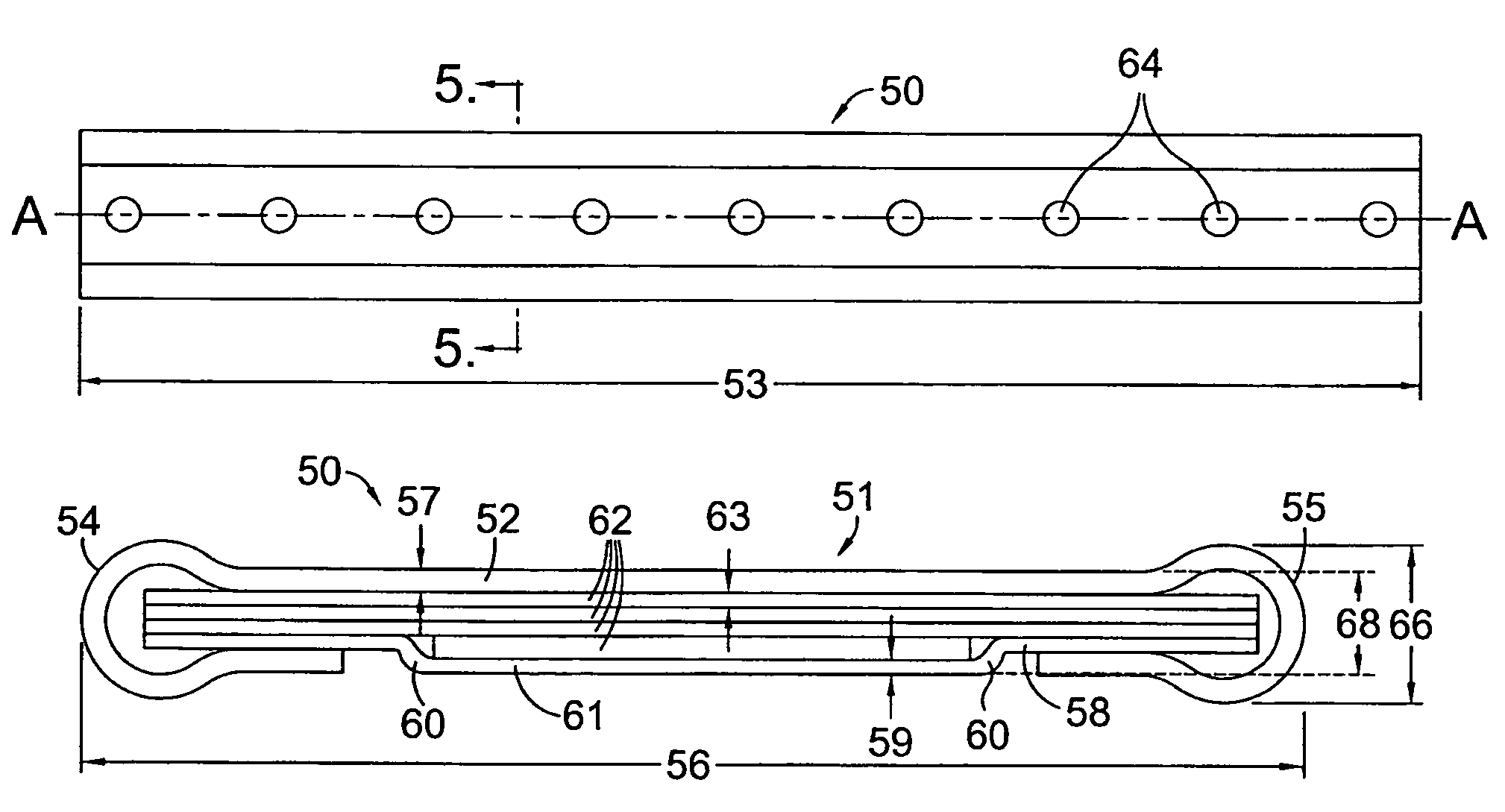
[0016]The preferred embodiment of the present invention is shown in detail in FIGS. 4-6. FIG. 4 depicts an elevation view of seal 50 in accordance with the preferred embodiment of the present invention with FIG. 5 taken as a cross section through the elevation view of FIG. 4. Seal 50 comprises an outer sleeve 51 having a first generally planar member 52 including length 53, first rounded end 54, second rounded end 55, and width 56 extending therebetween. Outer sleeve 52 also has a first thickness 57. Seal 50 further comprises a second generally planar member 58 that is opposite, yet substantially parallel to first generally planar member 51, as is shown in FIG. 5. Second generally planar member 58 has a second thickness 59 and at least one step 60 thereby forming a raised portion 61 of second generally planar member 58.
[0017]Located in between first generally planar member 52 and second generally planar member 58 is a plurality of third generally planar members 62 that each have a t...
PUM
 Abstract
Description
Claims
Application Information