Ground fault circuit interrupter (GFCI) end-of-life (EOL) status indicator

a ground fault and circuit interrupter technology, applied in the direction of circuit-breaking switches, emergency protective arrangements for limiting excess voltage/current, protective switch details, etc., can solve the problem of device trips, miswiring conditions are not easily detected, and serious injuries

Active Publication Date: 2008-02-26
HUBBELL INC
View PDF17 Cites 44 Cited by
  • Summary
  • Abstract
  • Description
  • Claims
  • Application Information

AI Technical Summary

Problems solved by technology

Generally, the ground fault condition results when a person or object comes into contact with the line side of the AC load and an earth ground at the same time, a situation which can result in serious injury.
The latter type of connection, which may result from a defective load or from improper wiring, is potentially dangerous because it can prevent a conventional GFCI device from tripping at the intended threshold level of differing current between line and neutral when a line-to-ground fault occurs.
When a ground fault occurs in the protected circuit, or when the test button is depressed, the GFCI device trips and an internal circuit breaker opens both sides of the AC line.
Because of the nature of the internal wiring of the GFCI receptacle, this miswiring condition is not easily detected.
In reality, however, no such protection is being provided because the AC source has been wired directly to the receptacle outlets without passing through the internal circuit breaker of the GFCI device.
Furthermore, a user may not know the state the GFCI is in without having to operate the test and reset buttons.
As a GFCI device is repeatedly tested or is frequently interrupting the power-supply circuit, its primary contacts begin to wear and, over time, the primary contacts do not have sufficient area or contact pad left to effectively withstand the severe electrical consequences of interrupting an energized circuit, in particular, arcing.
When the GFCI device primary contacts are at the end of their useful life, one of several possible failures is the welding together of the primary contacts.
This is a potentially hazardous condition because the conventional GFCI device has signaled a fault, but the appliance or tool that may be causing the fault is still connected to a power supply.
It is also possible that the conventional GCFI circuit would indicate that no fault has occurred, which would potentially harm a user through continued use of an appliance or tool that is in an unsafe condition.

Method used


Image

  • Ground fault circuit interrupter (GFCI) end-of-life (EOL) status indicator
  • Ground fault circuit interrupter (GFCI) end-of-life (EOL) status indicator
  • Ground fault circuit interrupter (GFCI) end-of-life (EOL) status indicator

Examples


Embodiment Construction

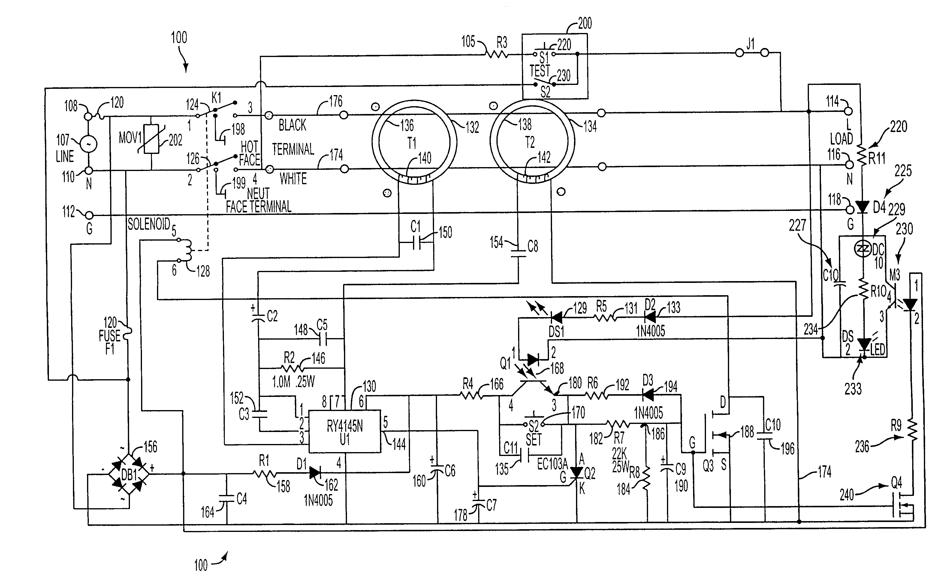
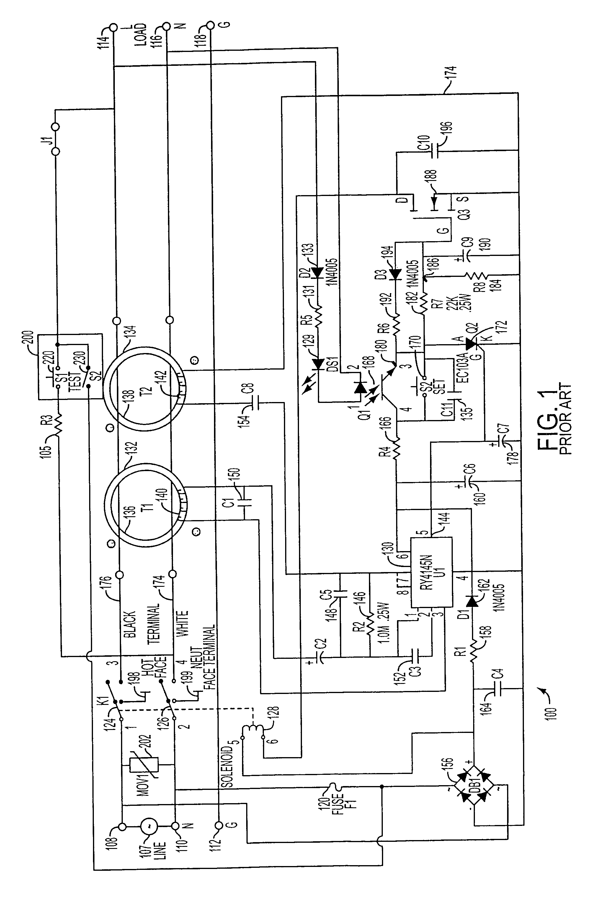
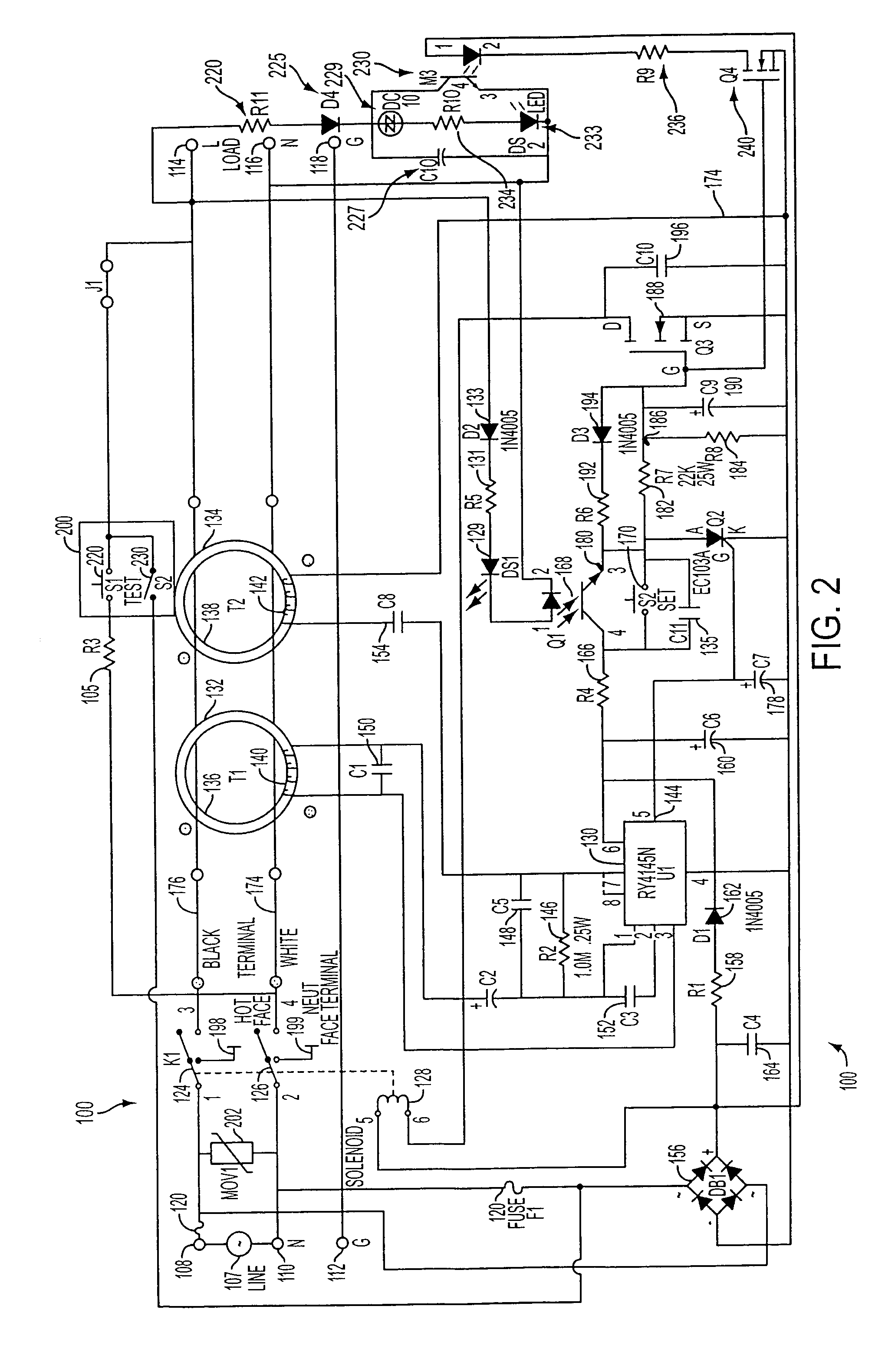
[0021]The typical operation of a conventional GFCI receptacle will be explained with reference to FIG. 1. Generally, it can be seen that a conventional ground fault circuit interrupter (GFCI) device 100 has an interrupt module comprising a relay with contacts 124 and 126, and a test switch 200 having primary test switch contacts 220 and secondary test switch contacts 230. The contacts 124 and 126 break a plurality of conductive paths between source terminals 108, 110 and load terminals 114, 116 of an AC receptacle in response to an imbalance of current flow in the paths.

[0022]The GFCI device 100 includes the pair of input (or source) terminals 108 and 110 which are adapted to be connected to the line (L) and neutral (N) terminals, respectively, of an AC power source 107. Within the GFCI device 100, a first conductor 176 connects the AC line input terminal 108 to a corresponding AC line output (or load) terminal 114, and a second conductor 174 connects the AC neutral input terminal 1...


PUM


Abstract

Disclosed is an end-of-life status alarm indication circuit and method for indicating the failure of the primary contacts of a ground fault circuit interruption (GFCI) device to open when a ground fault circuit is detected by the GFCI device. The GFCI device will protect against the situation where the primary contacts of a GFCI device become welded together and will not open when a ground fault circuit is detected by the device. The alarm indication may be either an audible or visual indication.

Description

CROSS-REFERENCE TO RELATED APPLICATIONS[0001]The present invention is related to U.S. Non-provisional patent application Ser. No. 11 / 497,515 of John R. Baldwin et al. entitled “SELF TESTING GROUND FAULT CIRCUIT INTERRUPTER (GFCI) WITH END OF LIFE (EOL) DETECTION THAT REJECTS FALSE EOL INFORMATION”, filed even date herewith , and U.S. Non-provisional patent application Ser. No. 11 / 198,400 of John R. Baldwin et al. entitled “SELF TESTING DIGITAL FAULT INTERRUPTER”, filed even date herewith, the entire contents of said applications being incorporated herein by reference.FIELD OF THE INVENTION[0002]The present invention relates generally to a ground fault circuit interrupter (GFCI) device that provides an indicator when a GFCI device has reached the end of its useful life. More particularly, the invention relates to a GFCI device that provides an indication that the primary contacts are still in the closed position even though a ground fault has been detected by the GFCI circuit.BACKGRO...

Claims


Application Information

Patent Timeline
Patent Type & Authority Patents(United States)
IPC IPC(8): H02H3/00H02H9/08H01H73/00
CPCH02H3/044H01H2071/044H02H3/334
Inventor LISCINSKY, III, STEPHEN M.
Owner HUBBELL INC
Why Eureka
Try Eureka