Pilot operated valve with a pressure balanced poppet

a technology of hydraulic valve and poppet, which is applied in the direction of fluid pressure control, process and machine control, instruments, etc., can solve the problems of electrical magnitude affecting the magnitude of pressure differential variation, and achieve the effect of counteracting the effect of valve operation

Active Publication Date: 2008-03-11
HUSCO INT INC
View PDF9 Cites 24 Cited by
  • Summary
  • Abstract
  • Description
  • Claims
  • Application Information

AI Technical Summary

Benefits of technology

[0011]Change in the pressure differential between control and pilot chambers alters the position of the pilot valve seat with respect to the main poppet. The change in position counteracts the effects on valve operation due to variation of the pressure at the two ports.

Problems solved by technology

A drawback regarding conventional solenoid operated pilot valves results from effects produced by a pressure differential that develops across the valve.
As a result, variation of the pressure differential affects the magnitude of electrical current needed to operate the valve in the manner requested by the operator.

Method used


Image

  • Pilot operated valve with a pressure balanced poppet
  • Pilot operated valve with a pressure balanced poppet

Examples


Embodiment Construction

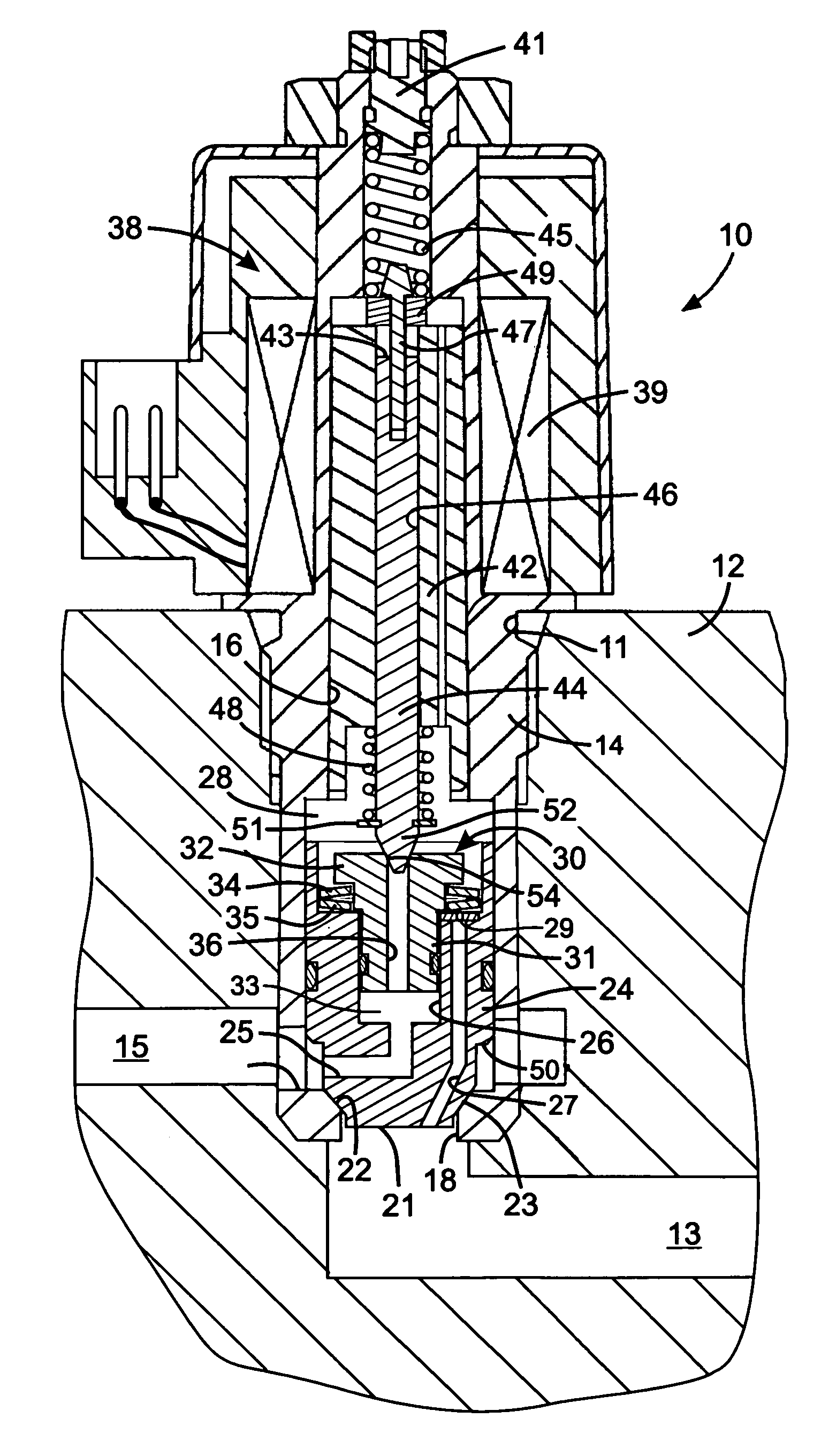
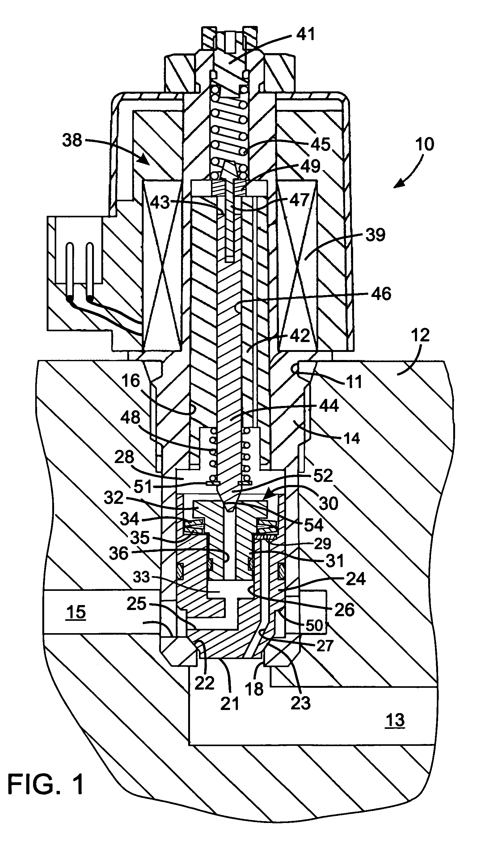
[0013]With reference to FIG. 1, a solenoid operated hydraulic valve 10 comprises a cylindrical valve body 14 that is mounted in an aperture 11 of a valve block 12. A first conduit 13 and a second conduit 15 in the valve block 12 open into the aperture 11. The valve body14 has a longitudinal first bore 16 with a first, or inlet port at one end and in communication with the first conduit 13. A second, or outlet, port 20 is formed in the side of the valve body 14 and is communicates with the second conduit 15. A valve seat 22 is formed in the first bore 16 between the first and second ports 18 and 20. Although the present invention is being described in the context of a unidirectional valve, that controls the flow of fluid from the first port to the second port, the novel concepts can be incorporated into bidirectional valves.

[0014]A main poppet 24 slides within the valve body first bore 16 and engages and disengages the valve seat 22 to selectively control flow of hydraulic fluid betw...


PUM


Abstract

A pilot operated valve has a main poppet that selectively controls flow of fluid between first and second ports in response to pressure in a control chamber on one side of the main poppet. The main poppet has an aperture extending between the control chamber and the first port. A pilot piston slides within the aperture and has the pilot passage with a pilot orifice and a first disk spring biases the pilot piston with respect to the main poppet. A pilot valve element selectively engages the pilot orifice to open and close the pilot passage and thereby controls motion of the main poppet. Forces from the first disk spring and a pressure differential between control and pilot chambers alter a position of the pilot valve seat with respect to the main poppet. The change in position compensates for effects on valve operation due to variation of the pressure at the two ports.

Description

BACKGROUND OF THE INVENTION[0001]1. Field of the Invention[0002]The present invention relates to pilot operated hydraulic valves, and more particularly to such valves that incorporate mechanisms which compensate for variation of a pressure differential across a pilot orifice.[0003]2. Description of the Related Art[0004]A wide variety of machines have moveable components which are operated by an hydraulic actuator, such as a cylinder and piston arrangement, that is controlled by a hydraulic valve. Traditionally, the hydraulic valve was manually operated by the machine operator. There is a present trend away from manually operated hydraulic valves toward electrical controls and the use of solenoid valves. This type of control simplifies the hydraulic plumbing as the control valves do not have to be located near an operator station, but can be positioned adjacent the actuator being controlled. This change in technology also facilitates computerized control of the machine functions.[000...

Claims


Application Information

Patent Timeline
Patent Type & Authority Patents(United States)
IPC IPC(8): F16K31/12
CPCF16K31/0689F16K31/0693G05D16/2097G05D16/2022
Inventor STEPHENSON, DWIGHT B.YANG, XIAOLONGJACKSON, RANDALL J.HUGHES, R. CHRISTOPHER
Owner HUSCO INT INC
Why Eureka
Try Eureka