Modular fuel injector and method of assembling the modular fuel injector

a fuel injector and modular technology, applied in the direction of fuel injector pumps, machines/engines, mechanical equipment, etc., can solve the problem that the injectors of known injectors cannot be tested

Inactive Publication Date: 2008-03-25
VITESCO TECH USA LLC
View PDF88 Cites 18 Cited by
  • Summary
  • Abstract
  • Description
  • Claims
  • Application Information

AI Technical Summary

Problems solved by technology

It is also believed that examples of known injectors can only be tested after final assembly has been completed.

Method used


Image

  • Modular fuel injector and method of assembling the modular fuel injector
  • Modular fuel injector and method of assembling the modular fuel injector
  • Modular fuel injector and method of assembling the modular fuel injector

Examples


Embodiment Construction

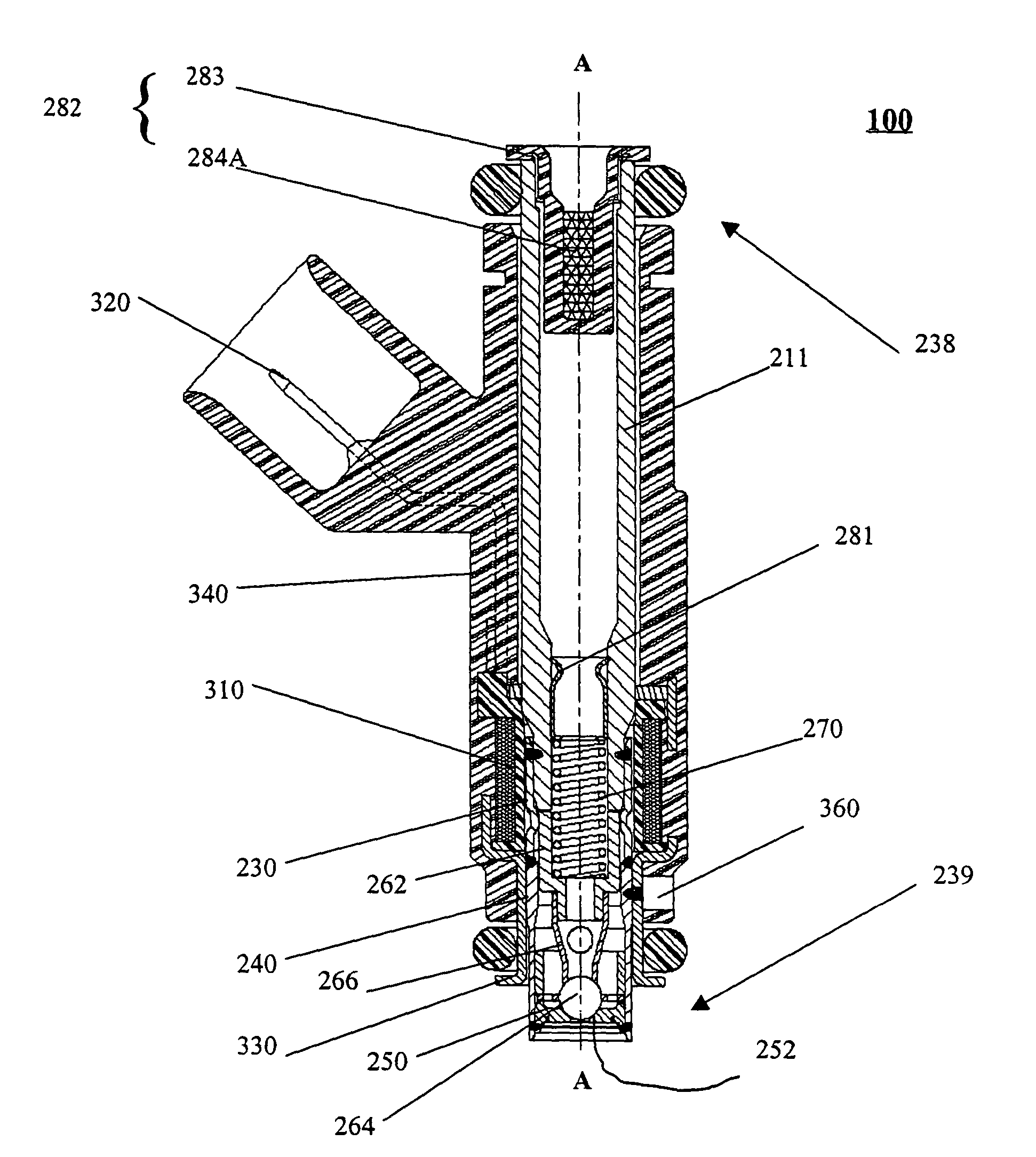
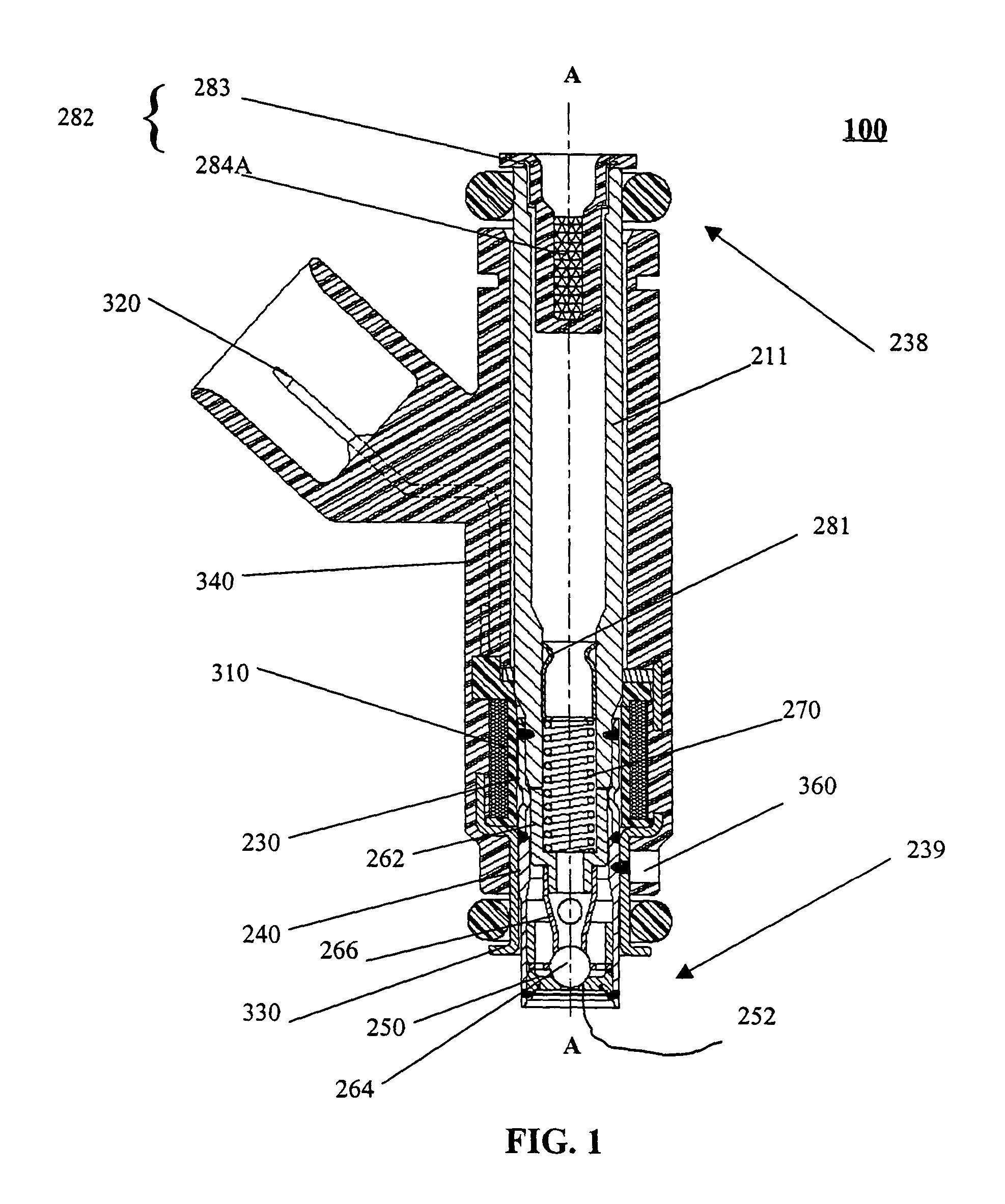
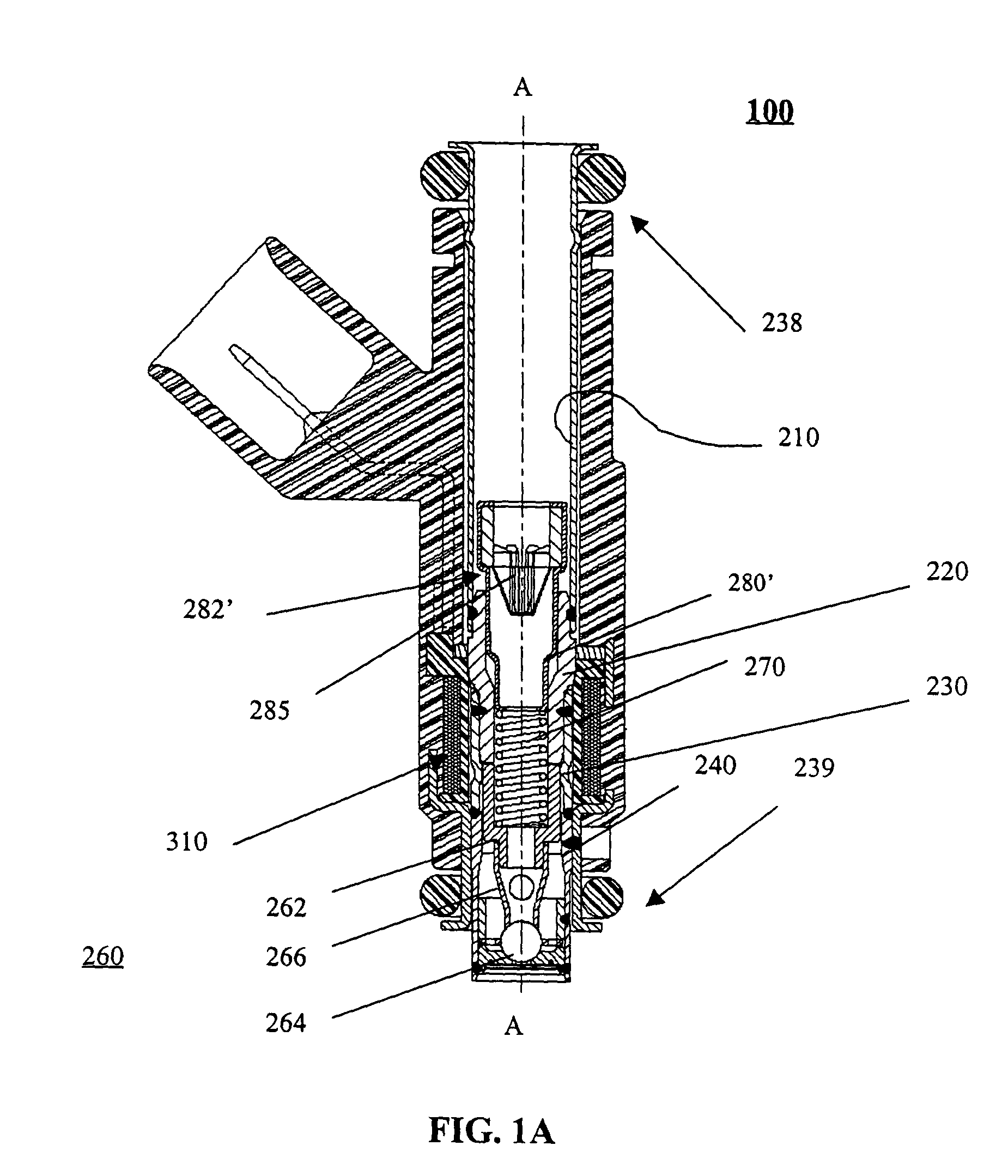
[0038]Referring to FIGS. 1-4, a solenoid actuated fuel injector 100 dispenses a quantity of fuel that is to be combusted in an internal combustion engine (not shown). The fuel injector 100 extends along a longitudinal axis between a first injector end 238 and a second injector end 239, and includes a valve group subassembly 200 and a power group subassembly 300. The valve group subassembly 200 performs fluid handling functions, e.g., defining a fuel flow path and prohibiting fuel flow through the injector 100. The power group subassembly 300 performs electrical functions, e.g., converting electrical signals to a driving force for permitting fuel flow through the injector 100.

[0039]Referring to FIGS. 1 and 2, the valve group subassembly 200 comprises a tube assembly extending along the longitudinal axis A-A between a first tube assembly end 200A and a second tube assembly end 200B. The tube assembly includes at least an inlet tube, a non-magnetic shell 230, and a valve body. The inle...


PUM


Abstract

A fuel injector for use with an internal combustion engine. The fuel injector comprises a valve group subassembly and a coil group subassembly. The valve group subassembly includes a tube assembly having a longitudinal axis that extends between a first end and a second end; a seat that is secured at the second end of the tube assembly and that defines an opening; an armature assembly that is disposed within the tube assembly; a member that biases the armature assembly toward the seat; an adjusting tube that is disposed in the tube assembly and that engages the member for adjusting a biasing force of the member; a filter that is at least within the tube assembly; and a first attachment portion. The coil group subassembly includes a solenoid coil that is operable to displace the armature assembly with respect to the seat; and a second attachment portion that is fixedly connected to the first attachment portion.

Description

[0001]This divisional application claims the benefit under 35U.S.C. §§ 120 and 121 of original application Ser. No. 09 / 828,487 filed on Apr. 9, 2001, now U.S. Pat. No. 6,676,044 which application is hereby incorporated by reference herein its entirety.BACKGROUND OF THE INVENTION[0002]It is believed that examples of known fuel injection systems use an injector to dispense a quantity of fuel that is to be combusted in an internal combustion engine. It is also believed that the quantity of fuel that is dispensed is varied in accordance with a number of engine parameters such as engine speed, engine load, engine emissions, etc.[0003]It is believed that examples of known electronic fuel injection systems monitor at least one of the engine parameters and electrically operate the injector to dispense the fuel. It is believed that examples of known injectors use electromagnetic coils, piezoelectric elements, or magnetostrictive materials to actuate a valve.[0004]It is believed that examples...

Claims


Application Information

Patent Timeline
Patent Type & Authority Patents(United States)
IPC IPC(8): F02D1/06B05B1/30B05B15/00F02M51/00F02M51/04F02M51/06F02M51/08F02M59/48F02M61/16F02M61/18F02M63/00
CPCF02M51/005F02M51/0614F02M51/0671F02M51/0682F02M61/168F02M61/18F02M61/188F02M61/165F02M2200/02F02M2200/16F02M2200/505F02M2200/9015F02M2200/9038F02M2200/9053F02M2200/9061Y10S239/19Y10S239/90
Inventor DALLMEYER, MICHAEL P.MCFARLAND, ROBERTHORNBY, MICHAEL J.PARISH, JAMES ROBERTBULGATZ, DENNISWOOD, ROSSHALL, BRYAN
Owner VITESCO TECH USA LLC
Why Eureka
Try Eureka