Port cover for limiting transfer of electromagnetic radiation from a port defined in a host device

a technology of host device and port cover, which is applied in the direction of screening casings, electrical equipment, aperture leaage reduction, etc., can solve the problems of inability to provide an interface between smart cards and certain host devices, inability to reduce the emission of electromagnetic radiation, and inability to provide a smart card interfa

Inactive Publication Date: 2008-04-01
THOMSON LICENSING SA
View PDF11 Cites 14 Cited by
  • Summary
  • Abstract
  • Description
  • Claims
  • Application Information

AI Technical Summary

Problems solved by technology

When multiple users share a common host device, each user may have a separate smart card having selected limitations, these limitations are triggered, e.g., when one user's smart card is removed from a host device and another user's smart card is inserted into the host device.
It is difficult to provide an interface between smart cards and certain host devices that emit certain ranges of electromagnetic radiation.
With a lack of an EMI shield over even a portion of the host device, electromagnetic interference (EMI), possibly including radio frequency interference (RFI), could escape from the satellite receiver into the surrounding space.
This large emission of EMI is unacceptable, since it does not conform with industry standards and can result in interference applied to electronic equipment located in the vicinity.

Method used


Image

  • Port cover for limiting transfer of electromagnetic radiation from a port defined in a host device
  • Port cover for limiting transfer of electromagnetic radiation from a port defined in a host device
  • Port cover for limiting transfer of electromagnetic radiation from a port defined in a host device

Examples


first embodiment

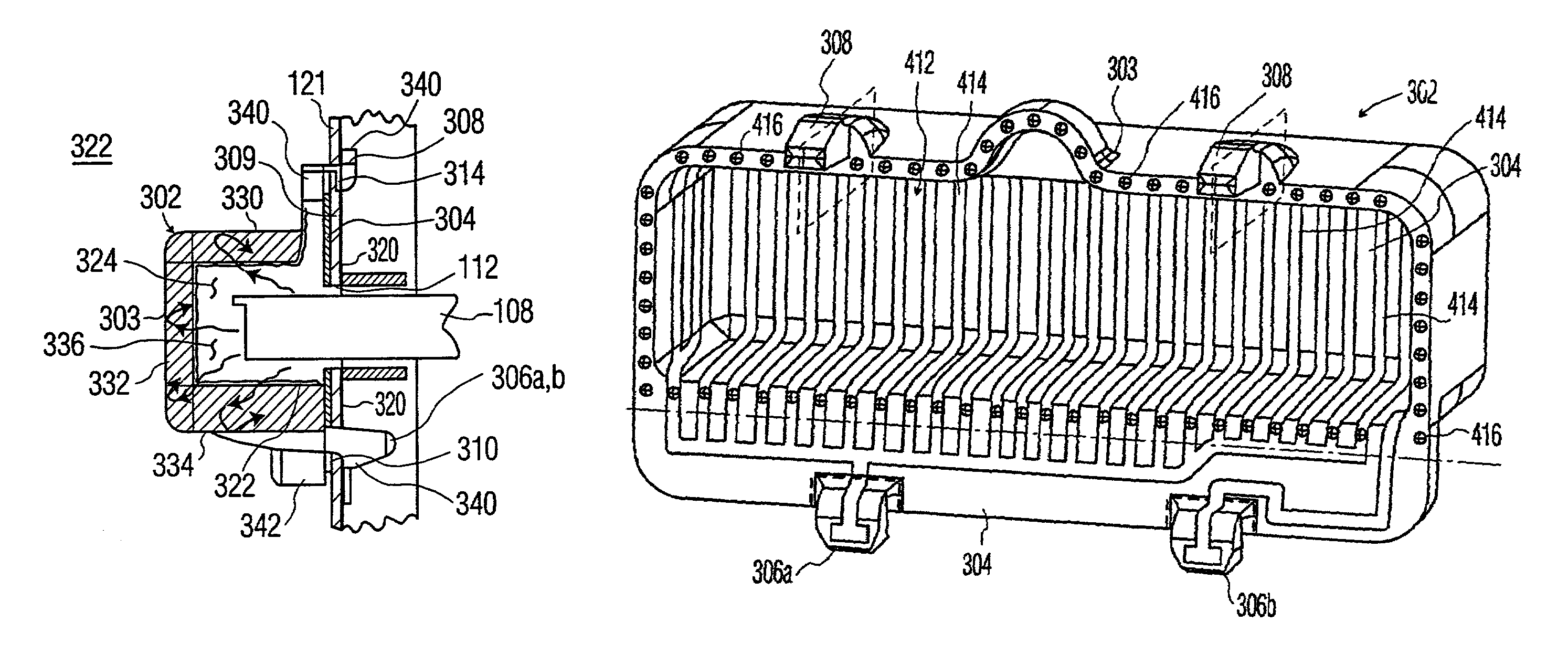
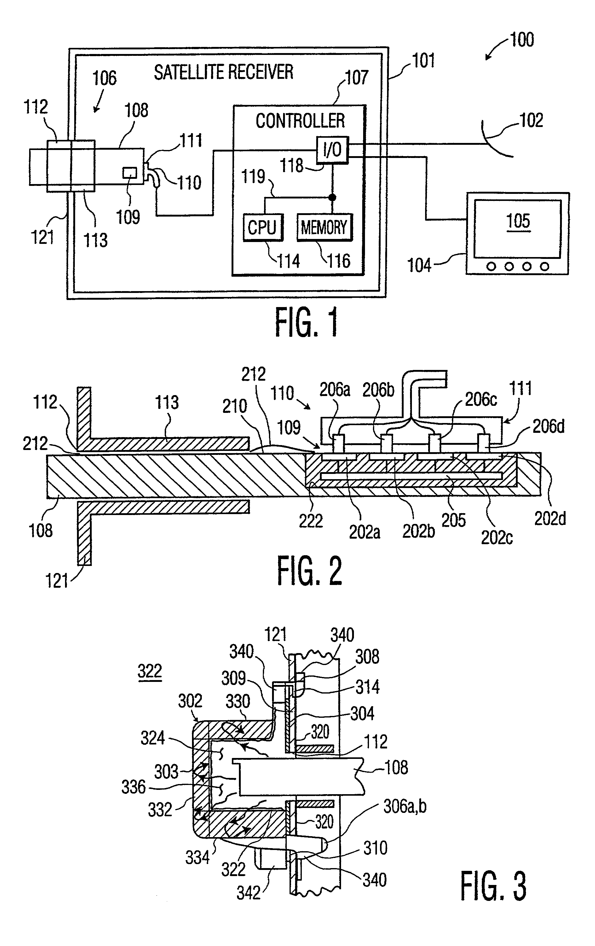
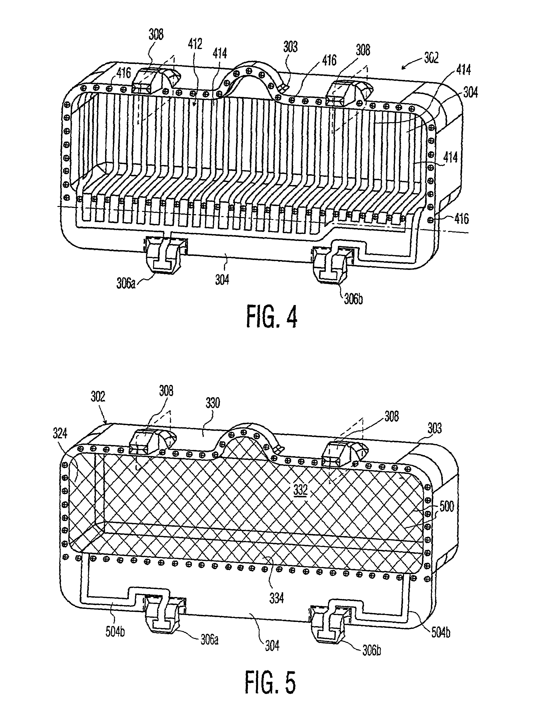
[0032]the present invention (depicted in FIG. 4) involves the use of a conductor trace 412. Conductor trace 412 functions to limit an unauthorized user from drilling through the port cover 302 such that hot-wired wires 212 can be passed through the holes in port cover 302. The conductor trace covers top portion 330, front portion 332, bottom portion 334, and the two side portions 336. The conductor trace 412 is to be configured such that if a hacker drills through the port cover 302 at any location that might provide access for the hot-wired wires 212, then at least one individual conductor 414 in conductor trace 412 will be severed. The individual conductors 414 of the conductor trace 412 are preferably arranged in parallel. Therefore, severing of any of the individual conductor(s) 414 will alter the electrical characteristics (e.g., the impedance) of the entire conductor trace 412. Therefore, the conductor trace can be monitored for changes in impedance, indicating tampering of po...

second embodiment

[0036]In applying conductor trace 412 to port cover 302 (depicted in FIG. 5 as taken relative to FIG. 3), the conductor trace 412 in the FIG. 4 embodiment is replaced by conductive plating 500 (shown by shading) applied to the port cover 302. More specifically, the conductive plating extends over top portion 330, front portion 332, bottom portion 334, and the two side portions 336. The conductive plating 500 is connected by insulated conductors 504a, 504b to coupling pads 306a, 306b, respectively. Alternatively, the above-described conductive plating and conductive powder technologies, described relative to the FIG. 4 embodiment, may be applied in this embodiment as well to form a substantially continuous conductor over the port cover 302. Insulated conductors 504a and 504b are depicted as attached to the surface of peripheral mounting surface 304 in FIG. 5, however the insulated conductors may actually be integrated in port cover 302. Conductive plating has empirically determinable...


PUM


Abstract

A port cover for covering a port formed in a host device, the port cover includes a bottom portion, a plurality of side portions, and couplers to attach the sides to a host device, where said couplers attach on either side of the port.

Description

[0001]This application claims the benefit under 35 U.S.C. § 365 of International Application PCT / US00 / / 17395, filed Jun. 23, 2000, which was published in accordance with PCT Article 21(2) on Jan. 25, 2001 in English; and which claims benefit of U.S. provisional application Ser. No. 60 / 143,844 filed Jul. 15, 1999.BACKGROUND OF THE DISCLOSURE [0002]1. Field of the Invention[0003]The invention relates to host devices. More particularly, the invention relates to a port cover for a host device.[0004]2. Description of the Prior Art[0005]Smart cards, and other similar information-storing devices, are known for their capabilities in storing information relating to stored funds, personal identification and other personal data, descrambling keys and an ability to access certain host devices. When multiple users share a common host device, each user may have a separate smart card having selected limitations, these limitations are triggered, e.g., when one user's smart card is removed from a ho...

Claims


Application Information

Patent Timeline
Patent Type & Authority Patents(United States)
IPC IPC(8): H05K9/00
CPCH05K9/0018
Inventor KNOKE, KEVIN CHARLESBISHOP, WILL ALLEN
Owner THOMSON LICENSING SA
Why Eureka
Try Eureka