Wireless power transmission system and method

a wireless power transmission and wireless technology, applied in the direction of antennas, antenna details, basic electric elements, etc., can solve the problems of many array elements being required to operate at less than full output power, not providing enough power to allow the system to operate with a high efficiency, and high efficiency of broad beam illumination. achieve the effect of minimal energy

Active Publication Date: 2010-10-14
RAYTHEON CO
View PDF10 Cites 323 Cited by
  • Summary
  • Abstract
  • Description
  • Claims
  • Application Information

AI Technical Summary

Benefits of technology

[0006]To overcome at least the drawbacks of other wireless power transmission systems, a system for wireless delivery of electromagnetic energy to multiple dispersed wireless power receivers

Problems solved by technology

Broad-beam illumination, however, is a highly inefficient method of illumination because most of the radiated power falls between the receivers and is wasted.
As a result, many array elements may be required to operate at less than full output power.
Becaus

Method used


Image

  • Wireless power transmission system and method
  • Wireless power transmission system and method
  • Wireless power transmission system and method

Examples


Embodiment Construction

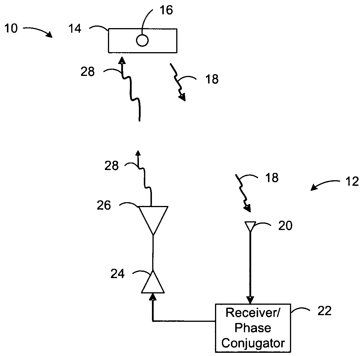
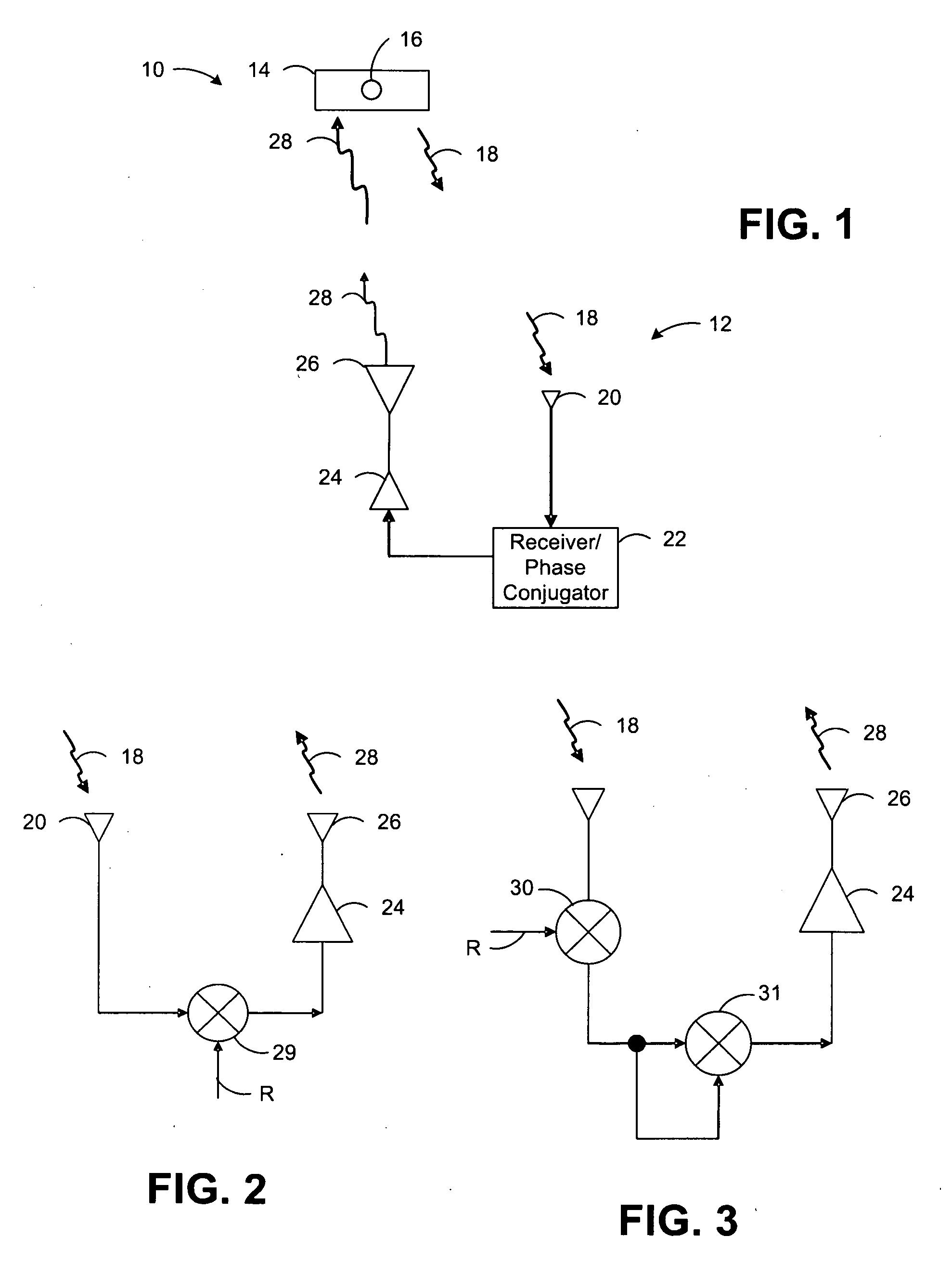
[0032]Referring initially to FIG. 1, a simplified block drawing is used to illustrate the basic operation of a switched beam wireless power transmission system 10. The system 10 includes at least one source of electromagnetic energy, such as an array of transmitting antennas 12, such as a retrodirective array of antennas (collectively referred to as an “RDA”), which may be, for example, parabolic reflecting antennas, phased array antennas, etc. The power generated by the at least one source of electromagnetic radiation can be divided among a plurality of antenna elements. For simplicity, the operation of a single transmitting antenna 12 is described.

[0033]Each element 12 in the RDA is used to illuminate or to transmit energy to one or more dispersed WPRs 14, which may be, for example, one or more rectennas or rectifying antennas.

[0034]Each WPR 14 is collocated with a beacon 16. The beacon 16 radiates a pilot signal 18 at a first frequency when the beacon 16 is in an active state. Th...


PUM


Abstract

A wireless power transmission system including at least one source of electromagnetic radiation, a plurality of wireless power receivers that receive radiated electromagnetic energy, a beacon collocated with each wireless power receiver, wherein the beacon generates and radiates a pilot signal when the beacon is in an active state, and an array of transmitting antennas connected to the source of electromagnetic radiation that radiates the electromagnetic radiation in the direction of the beacon in the active state. The electromagnetic radiation can be electronically steered from one wireless power receiver to another by activating and deactivating the beacons collocated with each wireless power receiver.

Description

FIELD OF THE INVENTION[0001]The present invention generally relates to the generation, transmission, and reception of wirelessly-transmitted power, and more specifically, to wireless power transmission systems capable of efficiently illuminating multiple dispersed wireless power receivers.DESCRIPTION OF THE RELATED ART[0002]Wireless power transmission is of increasing interest for both military and commercial applications. Potential applications include power transmission from space to earth and microwave-powered aircraft, whose applications include communications, reconnaissance, surveillance, and remote sensing (for a general discussion, see “The History of Power Transmission by Radio Waves” by William C. Brown, IEEE Transactions on Microwave Theory and Techniques, Vol. MTT-32, No. 9, pp. 1230-1242, September 1984).[0003]Some applications require the use of multiple dispersed wireless power receivers (WPRs). A broad-beam illumination of all receivers simultaneously can be implemen...

Claims


Application Information

Patent Timeline
IPC IPC(8): H01Q3/00
CPCH01Q3/2647H02J17/00H01Q21/28H01Q19/10H02J50/90H02J50/23H02J50/30H02J50/80H02J50/40
Inventor CROUCH, DAVID
Owner RAYTHEON CO
Why Eureka
Try Eureka