Electric heating devices and elements

a technology applied in the field of electric heating devices and elements, can solve the problems of high cost, ineffective use, and inconvenient maintenance, and achieve the effect of reducing both the inductive resistance and the electro-magnetic field

Inactive Publication Date: 2004-03-09
BAR KESER PROJECT MANAGEMENT INITIATIVES & ECONOMIC CONSULTANTS
View PDF31 Cites 13 Cited by
  • Summary
  • Abstract
  • Description
  • Claims
  • Application Information

AI Technical Summary

Benefits of technology

There is accordingly a need in the art to provide an electric heating device for heating an object to a required temperature that eliminates the need for thermo-insulating means or at least substantially reduces the requirements to such means.
Generally speaking, the present invention provides a method and device capable of a so-called "low-gradient" heating. In practice, in most cases it is desired to have substantially low gradient between the surface temperature of a heating device and the temperature of the heating object, so as to reduce the danger of fire, as well as the danger of burns, when applying a heating device to the body for medical purposes. Additionally, such a low-gradient heating enables to reduce the requirements of electro-and thermo-insulation, and to increase the effectiveness of heating (i.e., achieving a desired effect at minimal energy). This means that in order to create a high-quality heating device, its heating element, intended for heating a given object, should be independently designed and calculated, taking into account not only the power required to obtain a desired temperature of the object but also the fact that the surface temperature of the heating element should be as low as desired different from the required temperature of the heated object. This is a very complicated task, since the transfer of heat from the heating element towards the object is proportional to the temperature gradient (i.e., to the difference between the temperature of the heating element and the temperature of the heated object). Accordingly, the desired decrease of the temperature gradient should be compensated, and practically, the single solution for this is a maximal increase in the surface area of the heating element.
Owing to the fact that the voltage to be supplied to the heating element is a varying parameter selected in accordance with a specific application, a step-down transformer should be used in a heating device according to the invention. However, at the frequencies of the existing power networks (i.e., 50 Hz and 60 Hz), the weight and dimensions of such a transformer are significantly high, which sometimes makes the use of the transformer inefficient. The development of modern inverters practically allows for eliminating weight and dimensions related problem, since the weight and dimensions of a transformer are in inverse proportion to the working frequency thereof.
The present invention also provides the solution for the above problem. This is implemented by accommodating wires connecting the heating band to a power source in the following manner. One of the wires is connected directly to one of the outputs of the heating band. The other wire, on its way to the other output of the heating band, passes along the entire circuit of the band so as to be substantially symmetrical to the band along its longitudinal axis. This enables to sharply reduce both the inductive resistance and the electro-magnetic field.

Problems solved by technology

However, they suffer from a drawback arising out of the high working temperature of their heating elements which poses a safety hazard.
As is well known, electric radiators suffer from the disadvantages that they are expensive, heavy, and relatively inefficient

Method used


Image

  • Electric heating devices and elements
  • Electric heating devices and elements
  • Electric heating devices and elements

Examples


Embodiment Construction

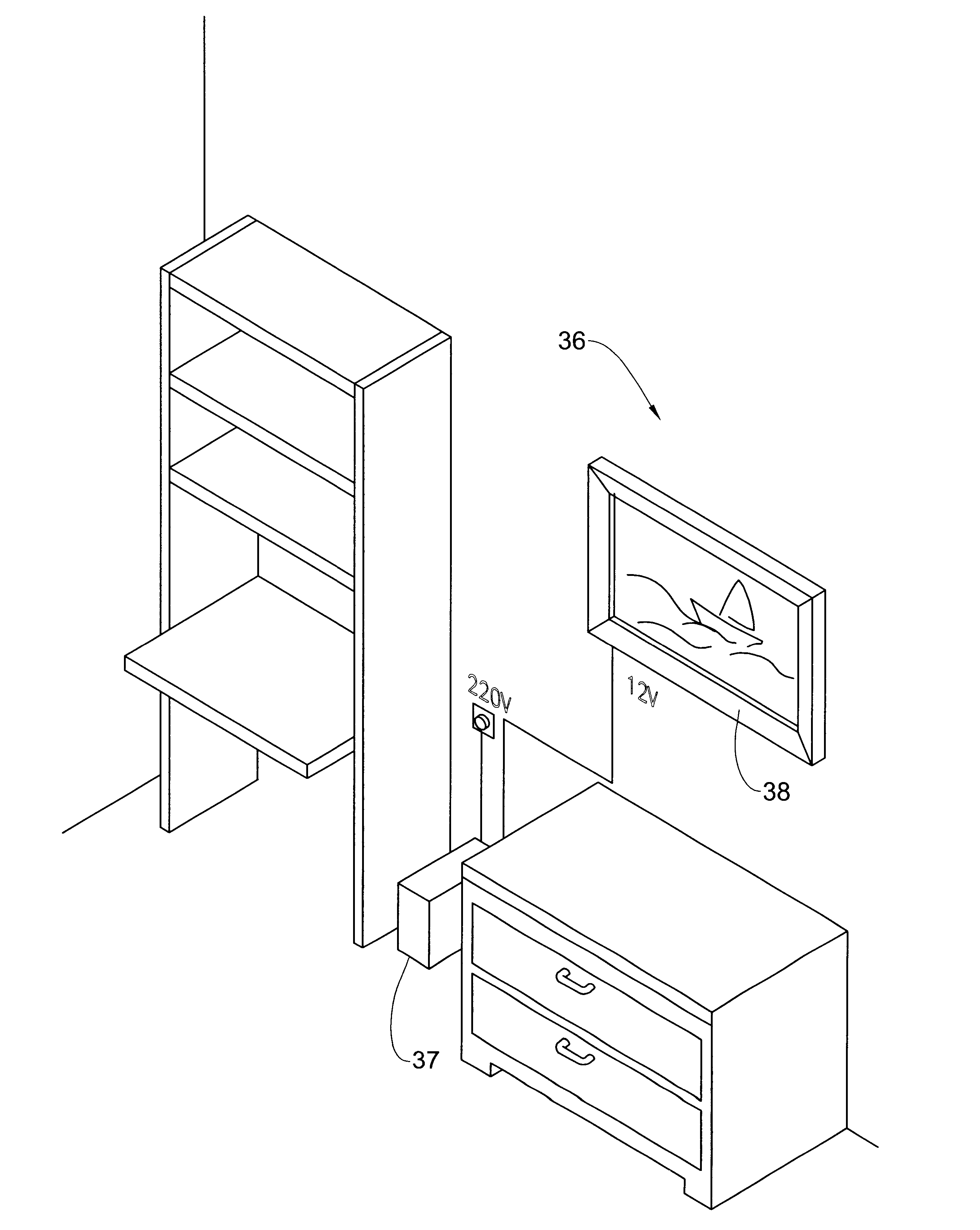
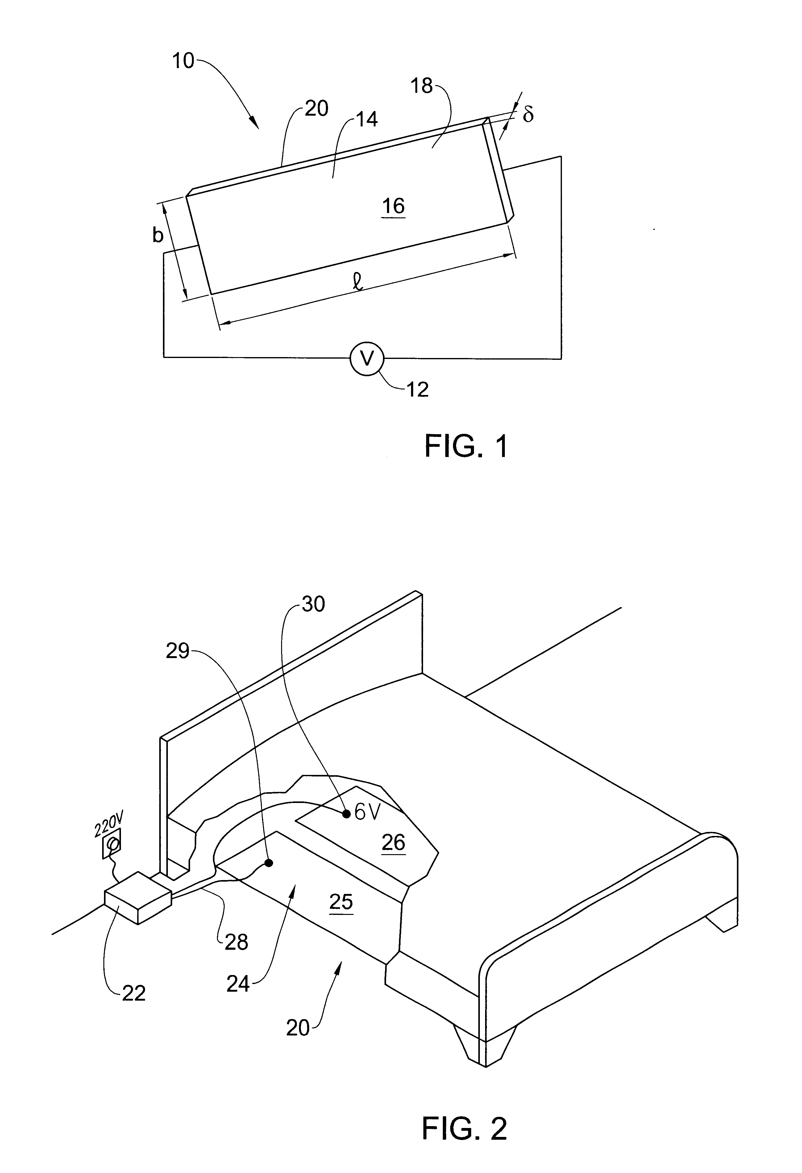
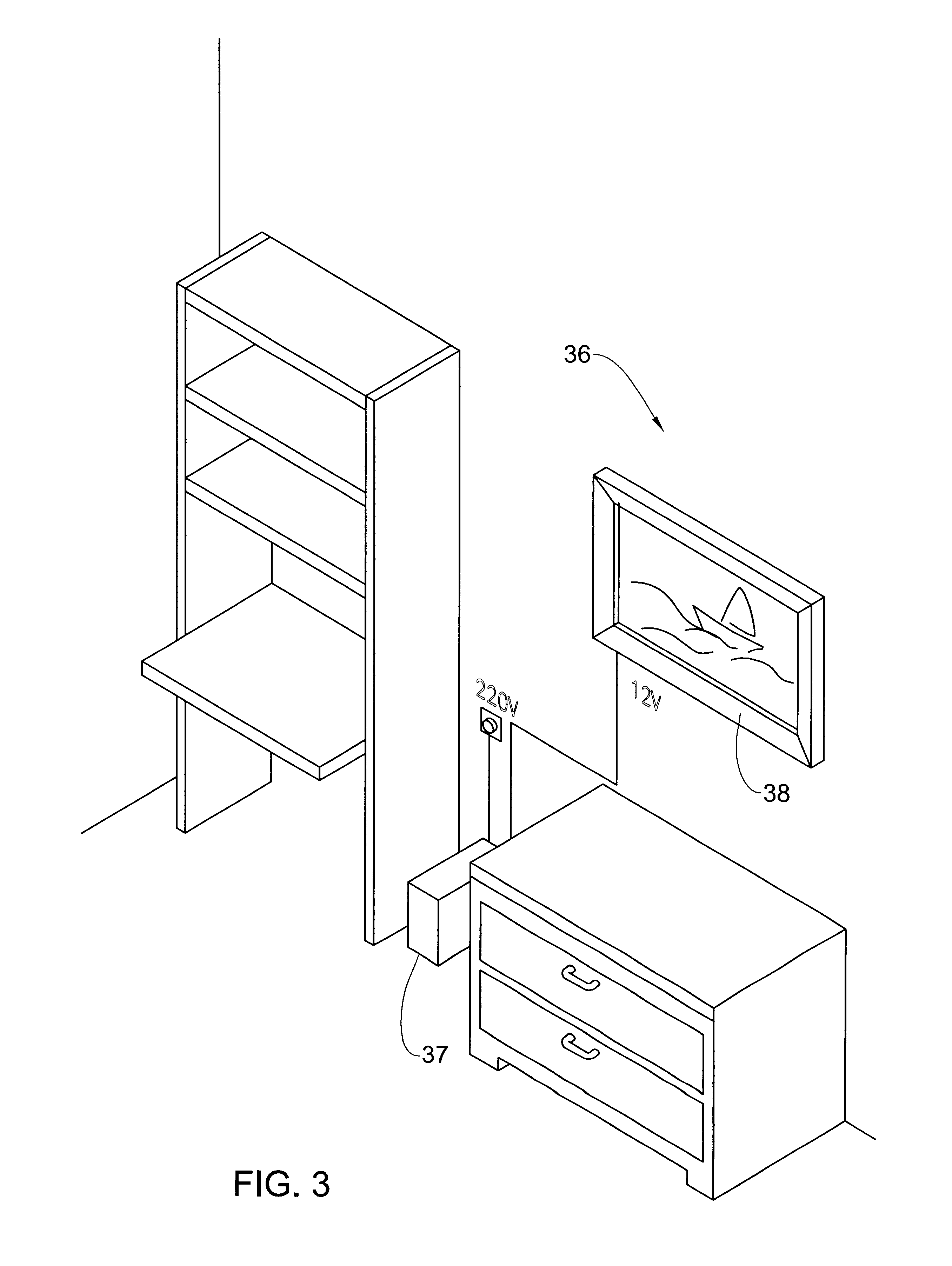
With reference now to the drawings, FIG. 1 shows an electric heating device, generally designated 10 connected to a source of electric energy 12 implemented as any one of a wide range of conventional DC and / or AC sources. Hence, the source of electric energy 12 can be implemented as a mains supply, a battery, a down-step transformer, and the like depending, inter alia, on the environment in which the electric heating device 10 is deployed.

In its simplest form, the electric heating device 10 is implemented as an electrically conductive heating element 14 fashioned as a relatively thin, generally rectangular cross sectioned, plate or band 16 having a length l, breadth b and a thickness .delta., so as to define front and back major surfaces 18 and 20, and side surfaces. In the case that the electric heating device 10 is free standing, the surface area S available to dissipate heat can be approximated as the combined surface area of the major surfaces 18 and 20. The combined surface are...


PUM


Abstract

Heating device having a substantially flat heating element with specifically selected physical parameters is provided for heating an object to a required temperature. The physical parameters are selected such as to, at a given power and at a selected voltage supply to the heating element, provide as low as desired temperature gradient between the temperature of the outer surface of the heating element through which beat is dissipated and the required temperature of the object. Heating devices of the invention may be implemented in domestic heaters, in food cooking devices, in medical devices, etc. Also provided is a method for designing heating elements for use in such devices.

Description

The present invention relates to electric heating devices in general and in particular to heating elements useful in such devices.Heating devices employed for household, industrial or other use have typically a heating element which is embedded within the device and which then transfers heat by radiation, convection or conductance to an output surface of the device. The temperature at the output surface of the device is thus much lower than the working temperature of the heating element. There is usually a very big temperature drop between the temperature of the heating element which ranges from 100's to 1,000's.degree. C., depending on the type of device, to a temperature at the output surface which may range from 60-90.degree. C. for household heating devices to 120-300.degree. C. for household cooling and baking devices.Heating devices come in a large variety of form and shape. For example, one type of electric heating device has a bare heating element typically fashioned as eith...

Claims


Application Information

Patent Timeline
Patent Type & Authority Patents(United States)
IPC IPC(8): H05B3/20H05B3/10H05B3/34A61F7/00
CPCH05B3/10H05B3/20H05B3/34A61F2007/0071H05B2203/013H05B2203/017H05B2203/021H05B2203/022H05B2203/032H05B2203/036
Inventor BIKHOVSKY, DAVID
Owner BAR KESER PROJECT MANAGEMENT INITIATIVES & ECONOMIC CONSULTANTS
Why Eureka
Try Eureka