Systems for and methods of three dimensional viewing

a three-dimensional and system-based technology, applied in the field of three-dimensional viewing systems, can solve the problems of reducing the resolution of the display to a large extent, not well adapted to viewing systems, and requiring lenses, prisms, or mirrors held in proximity with the viewer's eyes, etc., and achieve the effect of low cos

Inactive Publication Date: 2007-03-13
DISPLAY VECTORS LLC +1
View PDF9 Cites 221 Cited by
  • Summary
  • Abstract
  • Description
  • Claims
  • Application Information

AI Technical Summary

Benefits of technology

[0075]Particular adaptations of the head-tracking techniques for use in projection systems, with the aim of producing autostereoscopic systems at low cost, are presented.

Problems solved by technology

With respect to the first category, viewing apparatuses of the kind which require lenses, prisms, or mirrors held in proximity with the viewer's eyes, are generally less convenient than alternatives which do not require special eyeware and do not require the viewer using them to hold the apparatus or to approach his eyes to special eyepieces.
Lenticular systems which can be viewed from a large variety of viewing positions typically reduce the resolution of the display to a very large extent.
For this reason they are not well adapted for viewing systems such as computer displays and television and are therefore not in wide use.
As mentioned above, systems falling into these categories share a common disadvantage; they all require an inherent use of special eyeglasses or headgear.
The necessity for optical apparatus held near the eyes subtracts from the pleasure, comfort and naturalness of the experience of viewing the display, and may, depending on the system used, add significantly to the expense.
These and similar systems have the disadvantage of requiring use of polarizing eyeglasses.
Certain further disadvantages characterize systems which use polarizing glasses yet do not use switching means (c.f., fifth category).
An inherent disadvantage associated with such schemes is that part of the display surface is blocked from the view of each eye.
On the other hand, systems aimed at ensuring that all areas of the display space will be used in representing each of the left and right images (sequentially if not simultaneously) tend to be somewhat complex and are potentially relatively expensive to manufacture.
U.S. Pat. No. 5,083,851 to MacDonald provides an example of a system with undoubted qualities but which might be expensive to implement.
Yet, this projection system has the disadvantages of (i) requiring the viewer to wear eyeglasses, and (ii) requiring special projection devices which involve two projectors (or a specially designed single projector having the effect of two projectors) simultaneously projecting related pairs of images onto the screen.
Thus, this method calls for special projection equipment and, since it requires two separate light sources, it is not adaptable to standard computer displays nor to television displays.
Thus, in addition to the disadvantage of requiring the use of eye glasses, these systems prevent the use of natural color images.
Yet, these methods involve eyeglasses obligatorily worn by the viewer.
This inherent obligation however is a primary disadvantage.
Additional disadvantages of these systems include the complexity and thus expense of the shutter eyeglasses which must be connected to the display apparatus and simultaneously controlled, or alternatively (e.g. MacDonald) the increased complexity and expense of the display hardware itself.
Nevertheless, these solutions have the disadvantage of making the entire screen appear and disappear to each eye during each cycle, which tends to increase the impression of flickering of the screen.
As before, the principle disadvantage of the systems described by Bos and Liptoh is their dependence on eyeglasses worn by the viewer.
With respect to the sixth category, side-by-side implementations such as for example random dot stereograms are essentially methods for utilizing parallax information, are difficult to see for many viewers, convey only simplified images, and cannot convey color.
However, August's embodiments (as described in FIGS. 11, 12, and 13 therein) suffer from a major drawback that large percentages of the field of view of each eye (well more than half, according to August's drawings) are hidden from the eye at any given time, yielding a grainy low-resolution image.
However, Faris' invention is limited to a fixed position of the viewer with respect to the display during the whole time of viewing.
It, however, shares the limitations noted above, i.e., a significant percentage of the field of view is occupied by opaque regions which do not transmit either image, thereby limiting the resolution of the visible image and producing graininess.

Method used


Image

  • Systems for and methods of three dimensional viewing
  • Systems for and methods of three dimensional viewing
  • Systems for and methods of three dimensional viewing

Examples


Embodiment Construction

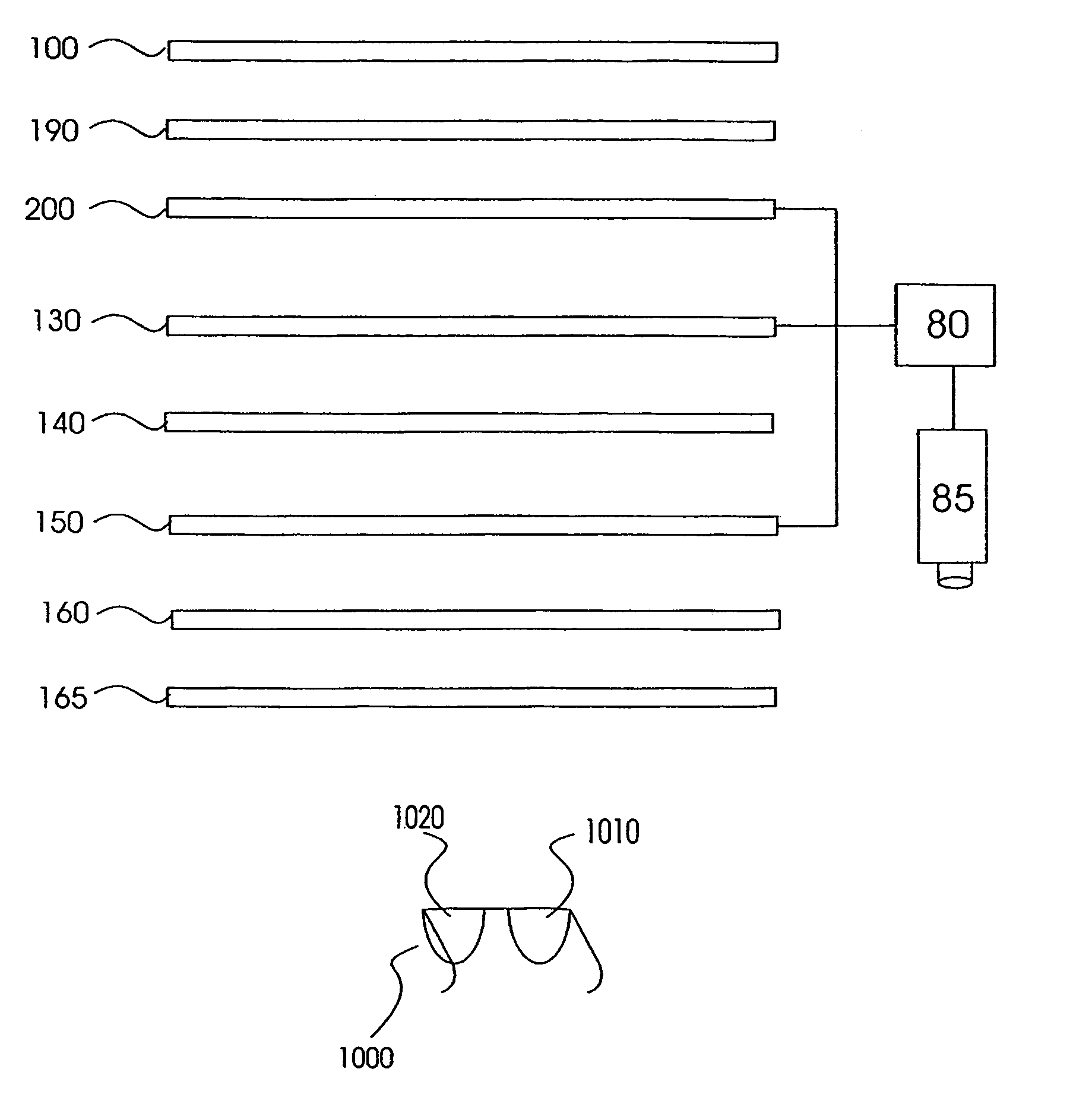
[0100]The present invention is of systems and methods which can be used for three-dimensional viewing, including three dimensional displays and projectors. In particular, the present invention provides improvements over prior art designs for three-dimensional viewing, such as the designs described in U.S. Pat. No. 5,822,117 to Kleinberger et al. and PCT Publication WO97 / 26577, as well as other prior art designs, as is specifically indicated below.

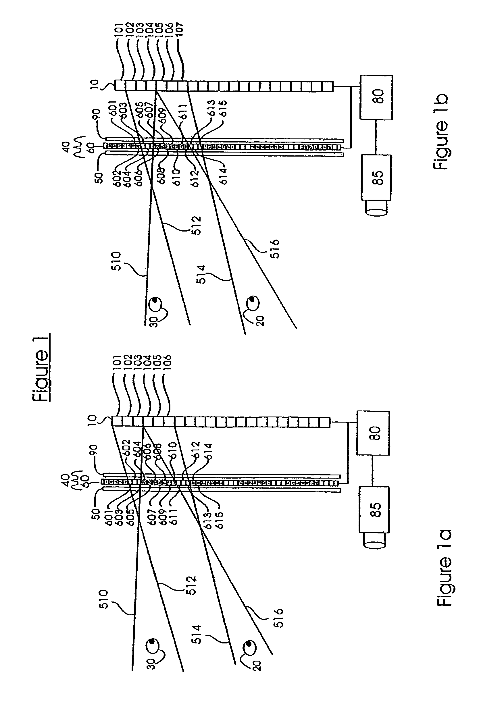
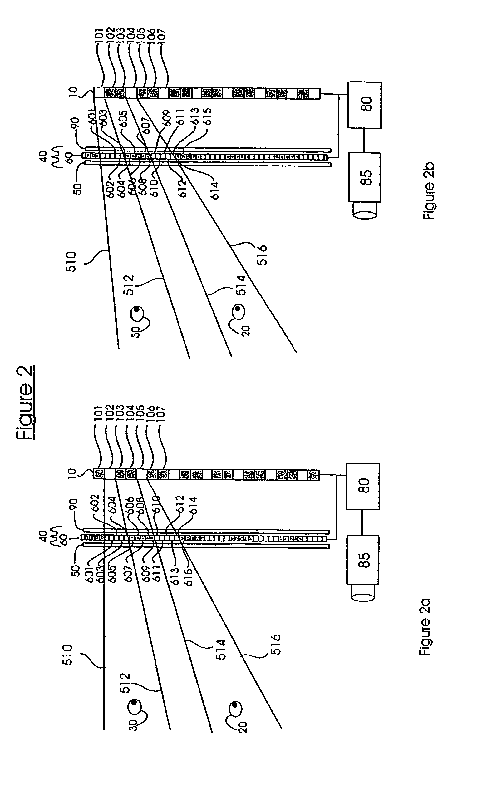
Improvements in Parallax Barrier Technology: Time-multiplexing of Elements of the Images

[0101]Classical parallax barrier systems have intrinsically low resolution, since 50% of the display surface is unavailable to each eye. They also have an intrinsically small sweet spot, since they depend on the left and right eyes being in particular positions with respect to the parallax barrier and the display, and if the eyes deviate from their expected positions a degradation of the perceived stereoscopic image is experienced. The movement-permissiv...


PUM


Abstract

The present invention relates in general to systems for and methods of three-dimensional viewing of displays and projections. One embodiment two layers (50, 90) are uniform polarizing filters and a birefringent layer with individually switchable elements (60) is sandwiched between them. Together these layers (50, 60, 90) constitute a parallax layer (40). This parallax layer (40) is located at a certain distance from a display (10). This placement, and the existence of opaque areas on the parallax layer (40) which permits to a viewer see a three-dimensional image. The individual elements (601–615) of the birefringent layer (60) are controlled by a control element (80), which is in communication with a head-tracking sensor (85). This allows the individual elements (601–615) of the birefringent layer (60) to be selectively turned on and off according to the position of the viewer's head.

Description

RELATED APPLICATIONS[0001]This application is a Continuation-In-Part (CIP) of U.S. patent application Ser. No. 09 / 987,793 filed on Nov. 16, 2001, now abandoned, which is a continuation of U.S. patent application Ser. No. 09 / 750,702, filed on Jan. 2, 2001, now abandoned, which is a continuation of U.S. patent application Ser. No. 09 / 101,984, filed on Jul. 21, 1998, now U.S. Pat. No. 6,252,707, issued on Jun. 26, 2001, which is a National Phase of PCT Patent Application No. PCT / US97 / 00778, filed on Jan. 21, 1997, now expired, which is a Continuation of U.S. patent application Ser. No. 08 / 657,227, filed on Jun. 3, 1996, now U.S. Pat. No. 5,822,117, issued on Oct. 13, 1998, which is a Continuation of U.S. patent application Ser. No. 08 / 589,510, filed on Jan. 22, 1996, now U.S. Pat. No. 5,973,831, issued on Oct. 26, 1999. PCT Patent Application No. PCT / US97 / 00778 also claims the benefit of Israel Patent Application No. 119437, filed Oct. 16, 1996, now abandoned.[0002]This Application is ...

Claims


Application Information

Patent Timeline
Patent Type & Authority Patents(United States)
IPC IPC(8): G02B27/26G02B30/25G02B30/27G02B30/30
CPCG02B27/0093G02B27/2214G02B27/26H04N13/0475H04N13/0409H04N13/0468H04N13/0404H04N13/305H04N13/31H04N13/366H04N13/373G02B30/25G02B30/27G02B30/30
Inventor KLEINBERGER, PAULKLEINBERGER, ILANMANTINBAND, JACK Y.GOLDBERG, HILLELKLEINBERGER, ELI
Owner DISPLAY VECTORS LLC
Why Eureka
Try Eureka