Disk drive with airflow channeling enclosure

a technology of airflow channeling and disk drives, applied in the field of disk drives, can solve problems such as disk flutter, disk vibration, disk force applied to actuator assemblies,

Inactive Publication Date: 2008-04-01
WESTERN DIGITAL TECH INC
View PDF28 Cites 111 Cited by
  • Summary
  • Abstract
  • Description
  • Claims
  • Application Information

AI Technical Summary

Problems solved by technology

Such interaction results in forces applied to the spindle motor hub that tend to rotate the spindle motor hub and the attached disks.
Further, such disk rotation induced airflow may result in a force applied to the actuator assembly, i.e., windage.
In addition, such disk rotation induced airflow may result in vibration of the disks or disk flutter.

Method used


Image

  • Disk drive with airflow channeling enclosure
  • Disk drive with airflow channeling enclosure
  • Disk drive with airflow channeling enclosure

Examples


Embodiment Construction

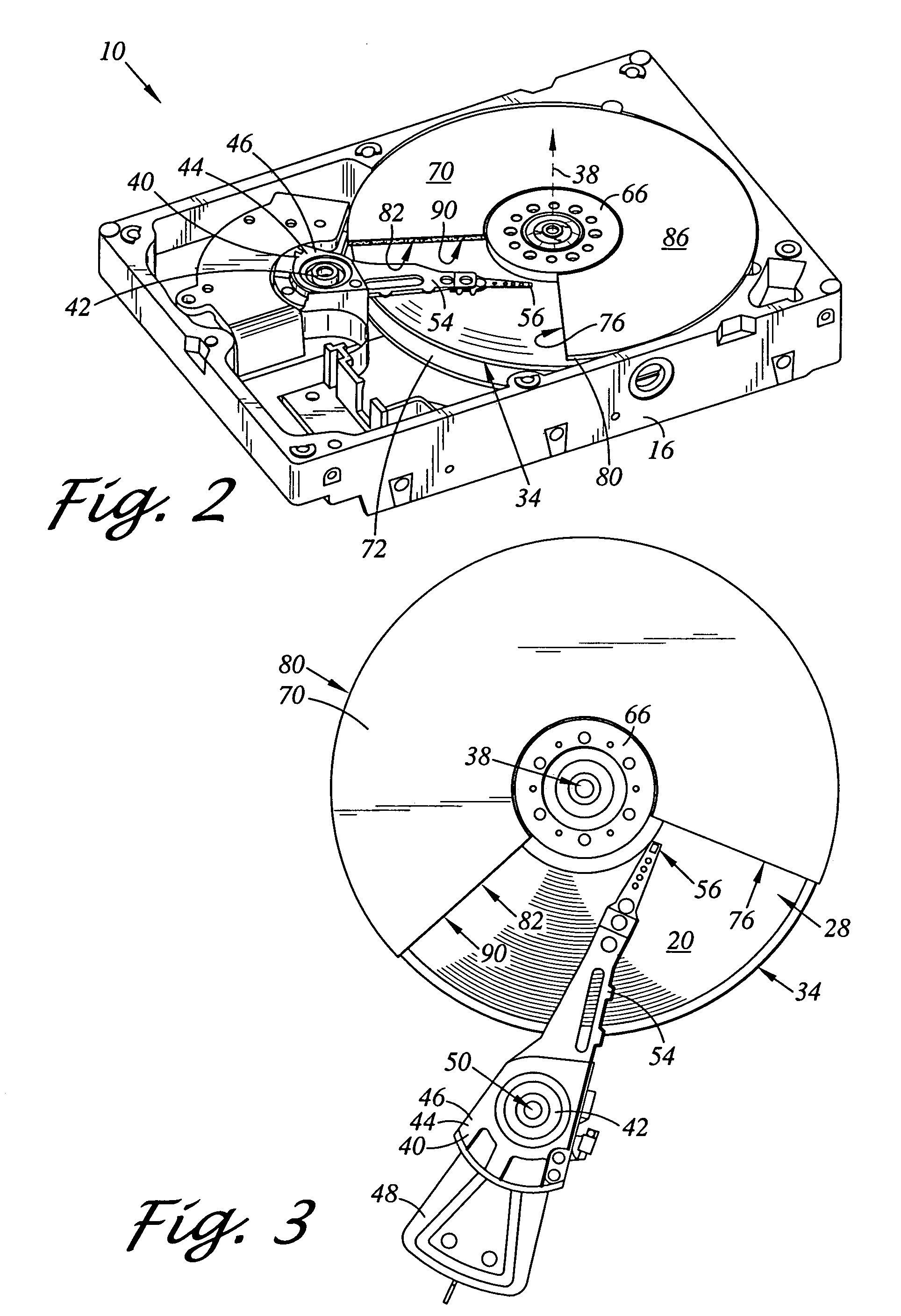
[0021]Referring now to the drawings wherein the showings are for purposes of illustrating preferred embodiments of the present invention only, and not for purposes of limiting the same, FIGS. 1-6 illustrate a disk drive including airflow channeling enclosures in accordance with aspects of the present invention.

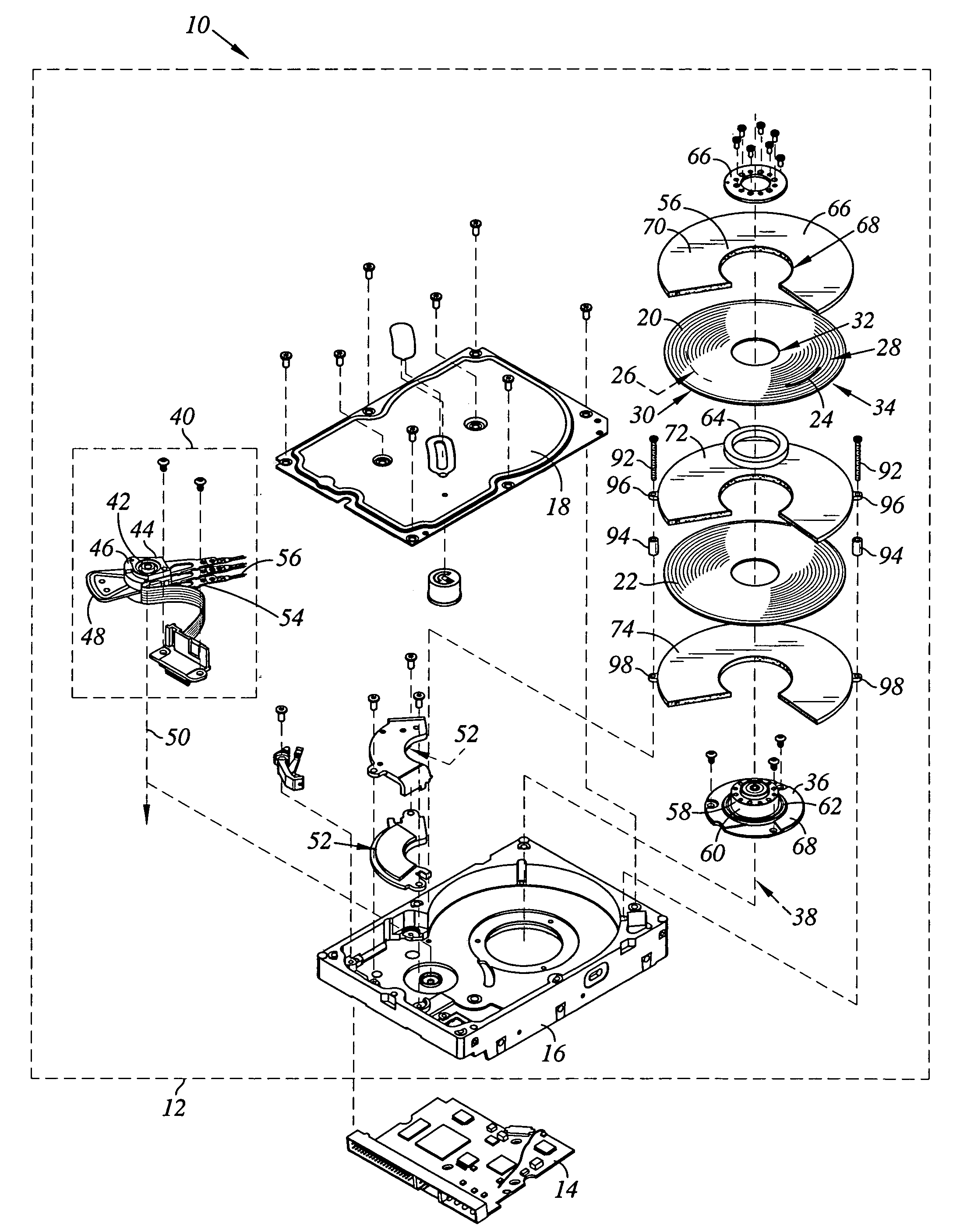
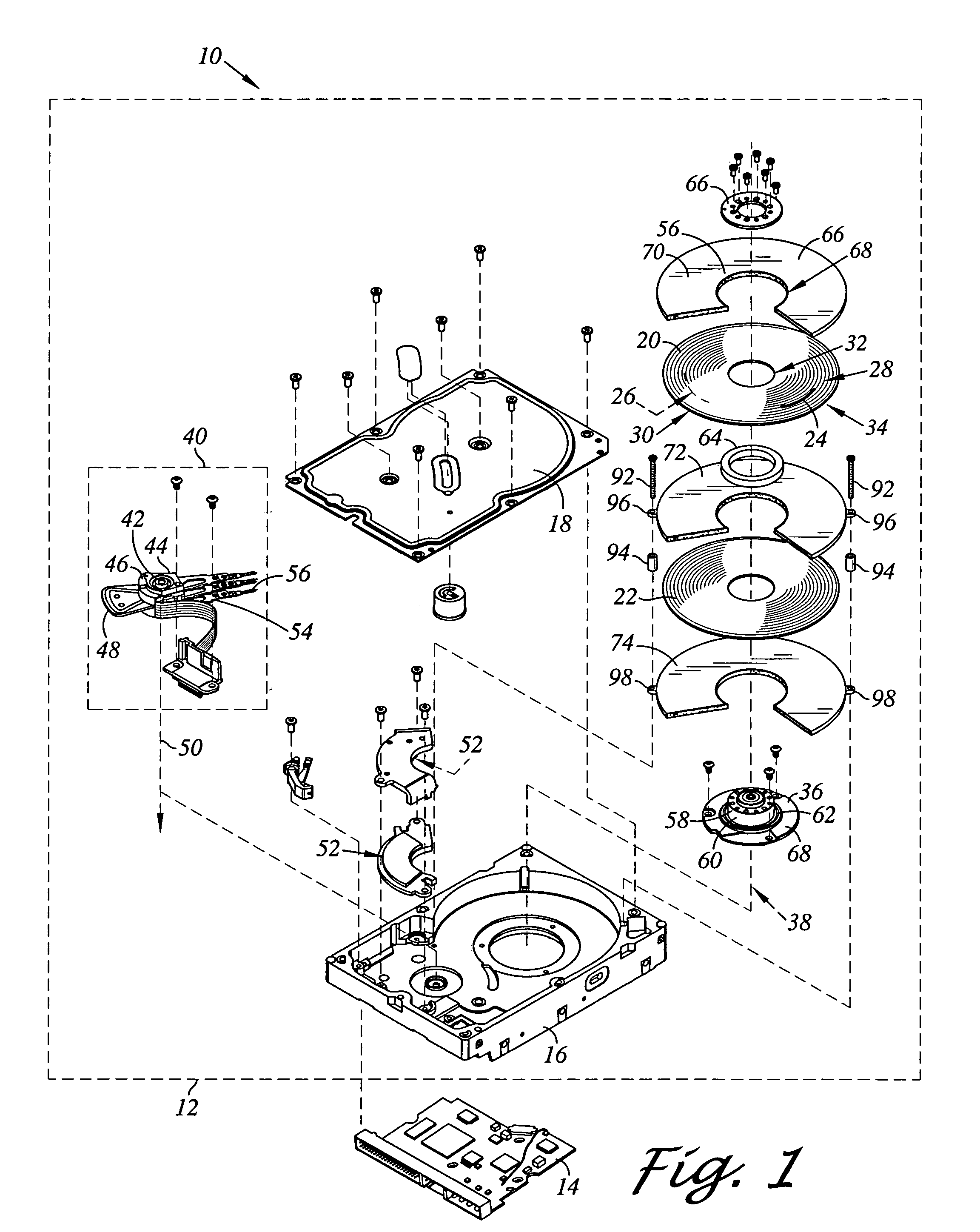
[0022]Referring now to FIG. 1 there is depicted an exploded perspective view of a disk drive 10 constructed in accordance with an aspect of the present invention. In the embodiment shown, the disk drive 10 includes a head disk assembly (HDA) 12 and a printed circuit board assembly (PCBA) 14. The head disk assembly 12 includes a housing which may include a disk drive base 16 and a cover 18 that collectively house magnetic disks 20, 22. Each magnetic disk 20, 22 contains a plurality of tracks for storing data. The disks 20, 22 may be two-sided, and thus for example, the magnetic disk 20 is shown having a track 24 on an upper disk surface 28 and a track 26 (shown in phantom) on a...


PUM

PropertyMeasurementUnit
axis of rotationaaaaaaaaaa
porosityaaaaaaaaaa
magnetic fieldaaaaaaaaaa

Abstract

A disk drive includes a disk drive base, a disk, and a head stack assembly rotatably coupled to the base adjacent the disk surface of the disk. The disk drive includes an airflow channeling enclosure. The enclosure includes an airflow inlet disposed downstream of the head stack assembly and configured to receive the disk rotation induced airflow therethrough. The enclosure further includes an airflow channel extending along the disk surface from the airflow inlet. The enclosure further includes an outer wall extending along the disk surface from the airflow inlet and defining the airflow channel radially interior to the outer wall. The enclosure further includes an airflow outlet disposed upstream of the head stack assembly extending from the outer wall and the channel opposite the airflow inlet for modifying the disk rotation induced airflow passing from the channel.

Description

BACKGROUND OF THE INVENTION[0001]1. Field of the Invention[0002]The present invention relates generally to disk drives, and in particular to a disk drive including an airflow channeling enclosure.[0003]2. Description of the Prior Art[0004]The typical hard disk drive includes a head disk assembly (HDA) and a printed circuit board assembly (PCBA) attached to a disk drive base of the HDA. The head disk assembly includes the disk drive base, a cover, at least one magnetic disk, a spindle motor for rotating the disk, and a head stack assembly (HSA) that includes a transducer head supported by a slider (collectively referred to as “head” or “slider”) for reading and writing data from and to the disk.[0005]The spindle motor includes a spindle motor hub that is rotatably coupled to the disk drive base. The spindle motor hub has an outer hub flange that supports a lowermost one of the disks. Additional disks may be stacked and separated with annular disk spacers that are disposed about the s...

Claims


Application Information

Patent Timeline
Patent Type & Authority Patents(United States)
IPC IPC(8): G11B33/14
CPCG11B5/6005G11B25/043G11B33/08G11B33/148G11B5/40
Inventor LIN, JEN-TAIOU-YANG, JIN HUIKU, CHIAO-PINGMCNAB, ROBERT J.CHEN, SHUO-HAOYANG, LIN
Owner WESTERN DIGITAL TECH INC
Why Eureka
Try Eureka