Plasma accelerator

a technology of accelerator and plasma, which is applied in the direction of accelerator, plasma technique, plasma, etc., can solve the problems of slow motion of magnetic pressure distribution, inability to accelerate plasma accelerator, and high potential for unstably applied current to the coil, so as to reduce mutual inductance, simplify the driving circuit, and accurately adjust the level and phase difference of current.

Active Publication Date: 2008-04-08
SAMSUNG ELECTRONICS CO LTD
View PDF5 Cites 11 Cited by
  • Summary
  • Abstract
  • Description
  • Claims
  • Application Information

AI Technical Summary

Benefits of technology

[0029]The present invention provides a plasma accelerator to reduce a mutual inductance between driving coils by winding the driving coils in opposite directions and connecting the driving coils to one another, to accurately adjust a level and a phase difference of currents to be applied to the coils, and to simplify a driving circuit.

Problems solved by technology

Therefore, the plasma accelerator cannot accelerate the plasma.
In this case, reducing a gap between coils and lowering a frequency of driving current makes the motion of the magnetic pressure distribution slow.
Due to the mutual inductances, the current is likely to be unstably applied to the coils.
The unstable level of current and the unstable phase difference cause an unstable operation of the plasma accelerator.

Method used


Image

  • Plasma accelerator
  • Plasma accelerator
  • Plasma accelerator

Examples


Embodiment Construction

[0053]Reference will now be made in detail to exemplary embodiments of the present invention, examples of which are illustrated in the accompanying drawings, wherein like reference numerals refer to the like elements throughout. Exemplary embodiments are described below to explain the present invention by referring to the figures.

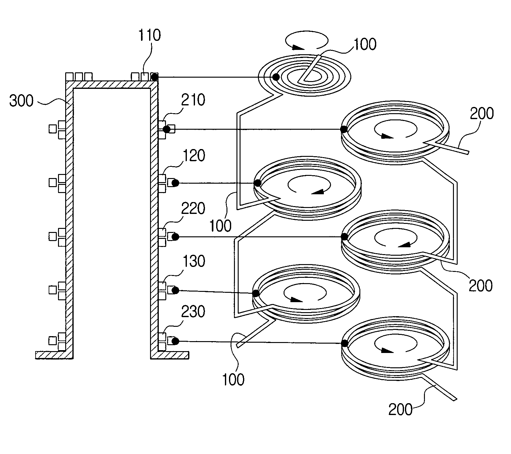
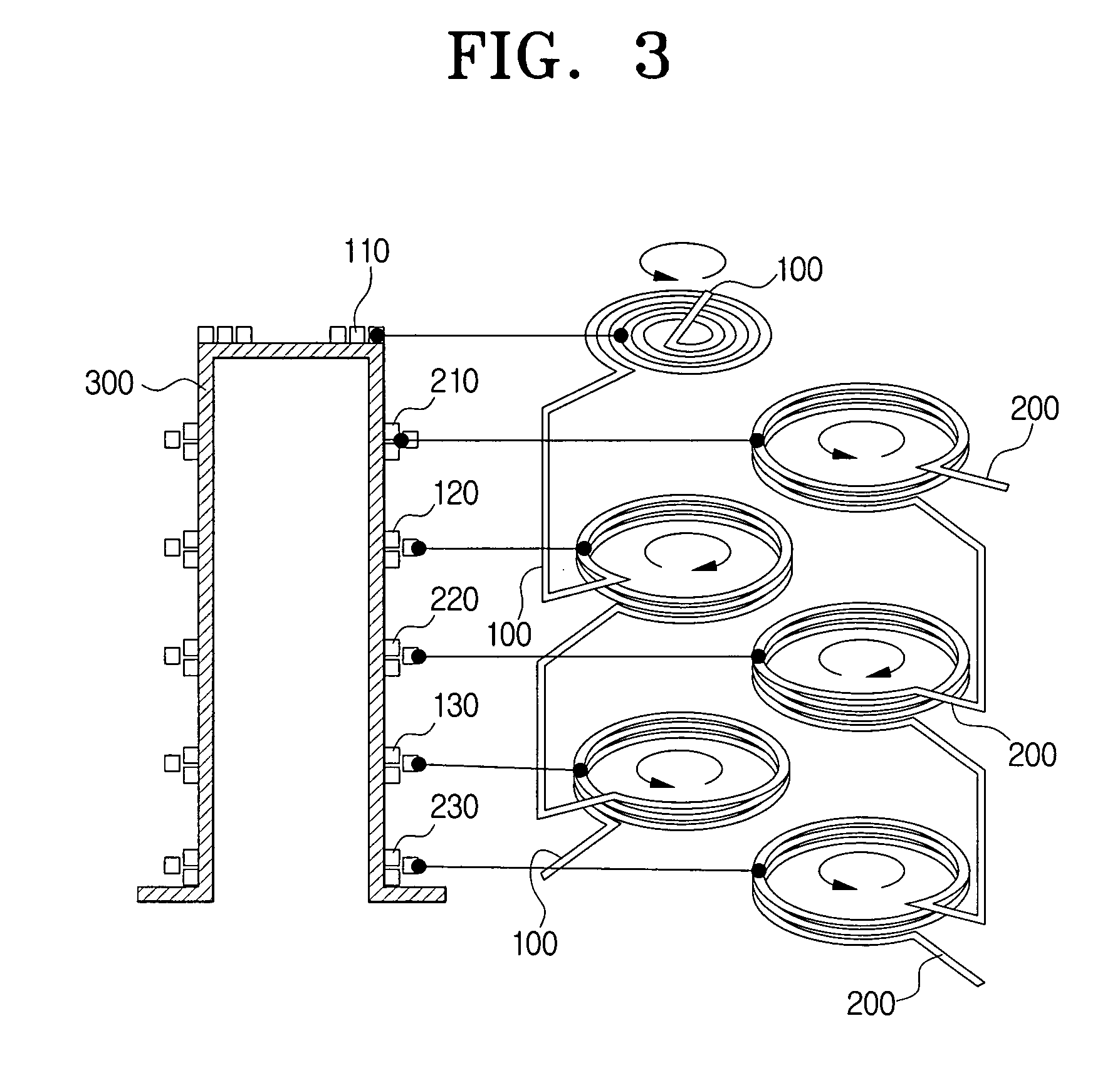
[0054]FIG. 3 illustrates a cross section of a plasma accelerator and a connection structure of coils according to an exemplary embodiment of the present invention.

[0055]Referring to FIG. 3, the plasma accelerator according to an exemplary embodiment of the present invention comprises a first coil section 100, a second coil section 200, and a chamber 300. The first coil section 100 comprises a top coil 110, a first coil 120 and a second coil 130. The second coil section 200 comprises a third coil 210, a fourth coil 220 and a fifth coil 230. The coils are wound in the directions of arrows. Although six coils (top coil through fifth coil) are discussed in this...


PUM


Abstract

A plasma accelerator is provided. The plasma accelerator includes a chamber having a closed top, an opened bottom and a lateral surface, a first coil section comprising a plurality of coils that are connected to one another in series and are wound around the lateral surface of the chamber in opposite directions, and a second coil section comprising a plurality of coils that are wound around the lateral surface of the chamber between coils of the first coil section in opposite directions. Accordingly, it is possible to make the mutual inductance between the coils small, to accurately adjust levels and phase differences of currents to be applied to the coils, and also to simplify the driving circuit.

Description

CROSS-REFERENCE TO RELATED APPLICATIONS[0001]This application claims the benefit of Korean Patent Application No. 10-2005-0090097, filed on Sep. 27, 2005, in the Korean Intellectual Property Office, the disclosure of which is incorporated herein by reference.BACKGROUND OF THE INVENTION[0002]1. Field of the Invention[0003]The present invention relates to a plasma accelerator, and more particularly, to a plasma accelerator which winds driving coils in opposite directions and connects the driving coils with one another, thereby reducing a mutual inductance between the driving coils and accurately adjusting levels and phase differences of currents applied to the driving coils, and also simplifies a driving circuit.[0004]2. Description of the Related Art[0005]A plasma accelerator accelerates flux of plasma generated or existing in a specific space using electric energy and magnetic energy and is called an ‘electro-magnetic accelerator’ (EMA).[0006]The plasma accelerator has been develope...

Claims


Application Information

Patent Timeline
Patent Type & Authority Patents(United States)
IPC IPC(8): H05H9/00
CPCF03H1/00H01L21/67063H05H1/54
Inventor PARK, WON-TAEKPASHKOVSKI, VASILYTOLMACHEV, YURI
Owner SAMSUNG ELECTRONICS CO LTD
Why Eureka
Try Eureka