Rapid response permanent magnet control mechanism

A technology of permanent magnet operation and quick response, applied in the direction of the power device inside the switch, etc., can solve the problem that the power supply requires a lower control speed. The curve is difficult to be consistent, etc., to reduce the refusal of the switch, prevent the coil from burning, and simplify the structure.

Inactive Publication Date: 2009-08-19
SOUTHEAST UNIV
View PDF0 Cites 4 Cited by
  • Summary
  • Abstract
  • Description
  • Claims
  • Application Information

AI Technical Summary

Problems solved by technology

[0003] (1) In order to obtain a larger electromagnetic force, the number of starting ampere-turns must be increased, which is contrary to the safety and reliability of the equipment
In particular, it is easy to cause the coil to burn out, and there are also considerable requirements for the parameters of the coil
[0004] (2) The load characteristic cur...

Method used


Image

  • Rapid response permanent magnet control mechanism
  • Rapid response permanent magnet control mechanism
  • Rapid response permanent magnet control mechanism

Examples


Embodiment Construction

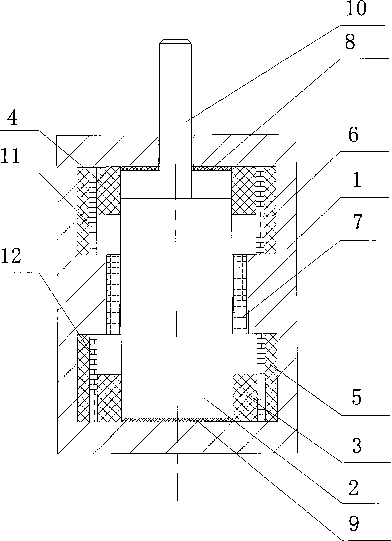
[0028] refer to figure 1 , a fast-response permanent magnet operating mechanism for switch control, including: a yoke 1, a moving iron core 2 and a push rod 10, the top of the moving iron core 2 is provided with a push rod 10, and the moving iron core 2 is set on the magnetic Inside the yoke 1, the opening coil 3, the closing coil 4, the opening starting coil 5, the closing starting coil 6, the annular permanent magnet 7, the upper buffer pad 8, and the lower buffer pad 9 are also arranged in the yoke 1 , the upper insulating layer 11 and the lower insulating layer 12, and the closing coil 3 is located on the top of the inner wall of the yoke 1 and sleeved on the moving iron core 2, and the upper buffer cushion 8 is fastened on the top of the inner wall of the yoke 1 and sleeved On the push rod 10, the opening coil 4 is located at the bottom of the inner wall of the yoke 1 and sleeved on the moving iron core 2, the lower buffer cushion 9 is fastened at the bottom of the inner...


PUM


Abstract

The invention discloses a fast response permanent magnetic operating mechanism used for switch operation, which comprises a magnetic yoke (1), a movable core (2) and a push rod (10), wherein, the top of the movable core (2) is provided with the push rod (10); the movable core (2) is arranged in the magnetic yoke (1) which is internally provided with a switch-off coil (3), a closing coil (4), a switch-off starting coil (5), a closing starting coil (6), an annular permanent magnet (7), an upper buffer cushion (8), a lower buffer cushion (9), an upper insulation layer (11) and a lower insulation layer (12). The switch-off and closing coils are used for providing electromagnetic attraction for the movable core during switch-off and closing processes of the switch so as to offset the attraction of the annular permanent magnet to the movable core; and the switch-off and closing starting coils are used for providing electromagnetic attraction for the movable core at the initial stage of switch-off and closing of the switch so as to offset the attraction of the annular permanent magnet to the movable core. The annular permanent magnet is used for providing switch-off and closing power and keeping a movable contact of the switch to be in the switch-off and closing position. The magnetic yoke is used for providing a magnetic circuit; the movable core is used for driving the moving part of the switch to move; and the buffer cushions is used for absorbing the impact of vibration.

Description

technical field [0001] The invention is primary equipment of a power system, which belongs to an accessory of a switchgear, and is a driving device for providing power for a switch to open and close. The invention particularly relates to a quick-response permanent magnet operating mechanism. Background technique [0002] The permanent magnet operating mechanism is a successful example in the process of digitization of the operating mechanism, but further research is needed to expand the permanent magnet mechanism to the high-voltage field: [0003] (1) In order to obtain a larger electromagnetic force, the number of initial ampere-turns must be increased, which is contrary to the safety and reliability of the equipment. In particular, it is easy to cause the coil to burn out, and there are also considerable requirements for the parameters of the coil. [0004] (2) It is difficult for the load characteristic curve to be consistent with the electromagnetic attraction driving ...

Claims


Application Information

Patent Timeline
IPC IPC(8): H01H3/28
Inventor 郑建勇梅军张胄吴桂林
Owner SOUTHEAST UNIV
Why Eureka
Try Eureka