Surgical instrument for inserting intervertebral prosthesis

a technology for intervertebral prosthesis and surgical instrument, which is applied in the field of surgical instrument for inserting intervertebral prosthesis, can solve the problems of complex arrangement and do not give the operating surgeon an exact pictur

Active Publication Date: 2007-01-30
DEPUY SPINE INC (US)
View PDF12 Cites 82 Cited by
  • Summary
  • Abstract
  • Description
  • Claims
  • Application Information

AI Technical Summary

Benefits of technology

[0008]In an expedient configuration, the lever is not an integral component part of the instrument body, but instead is designed in such a way that it can be attached to the instrument body, and again released from it, during the operation. This has the advantage that the instrument body is not impeded by the spreading mechanism, formed by the lever, in those stages of the operation where spreading does not take place or does not have to be maintained. If the actuating lever is articulated on one of the two movable elements and acts on the other element via a limit stop, a longitudinal displacement may occur at the limit stop, between the limit stop and the limit stop mating surface, through which undesired frictional forces are generated. According to a further feature of the invention, provision is therefore made for the limit stop to act on the limit stop mating surface via a friction-reducing means. This friction-reducing means can, for example, be formed by a

Problems solved by technology

The use of forceps has the disadvantage that the forceps bows which the operating surgeon holds in the hand do not give him an exact picture of the orientation of the front end of the forceps and of the prosth

Method used


Image

  • Surgical instrument for inserting intervertebral prosthesis
  • Surgical instrument for inserting intervertebral prosthesis
  • Surgical instrument for inserting intervertebral prosthesis

Examples


Embodiment Construction

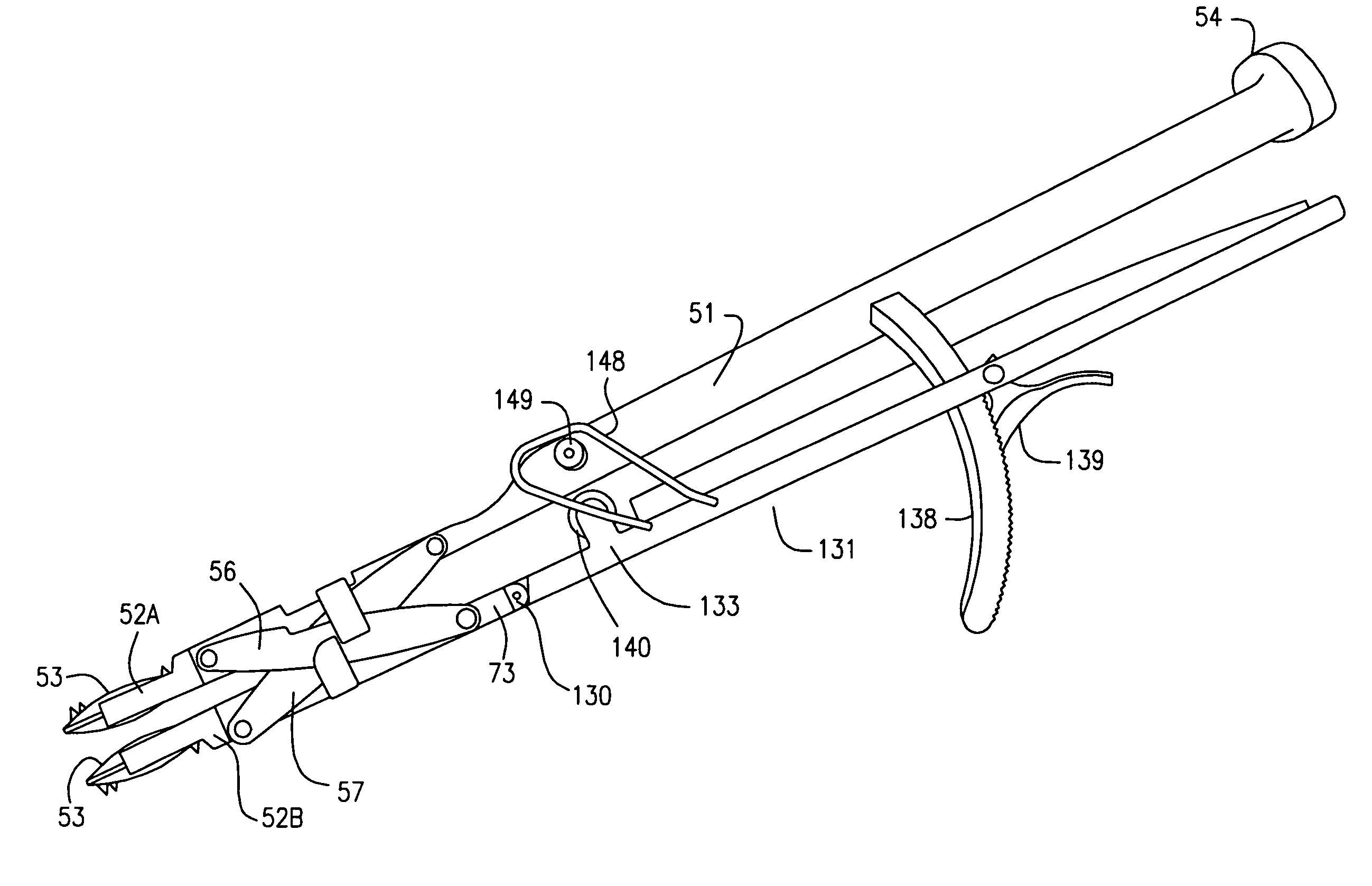
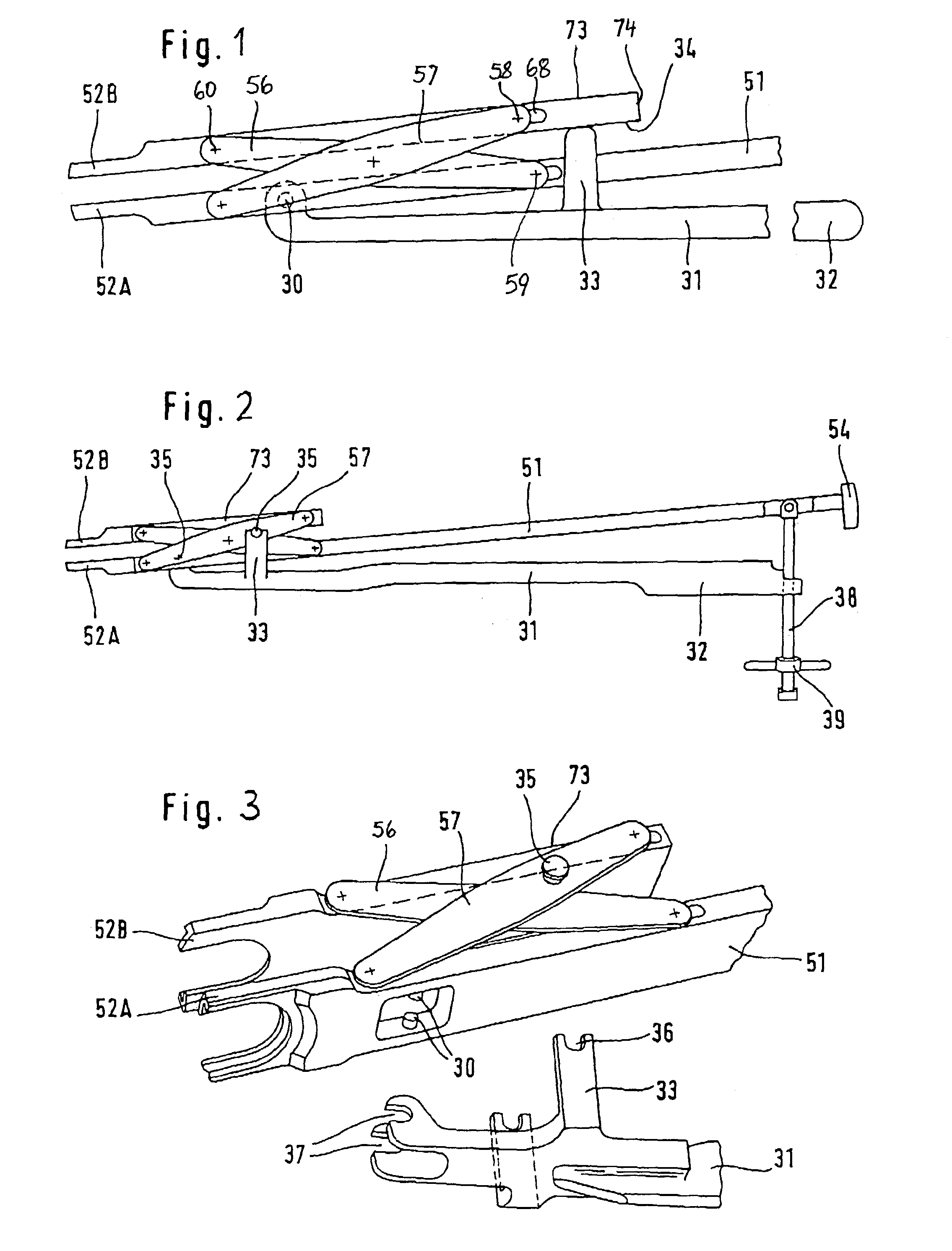
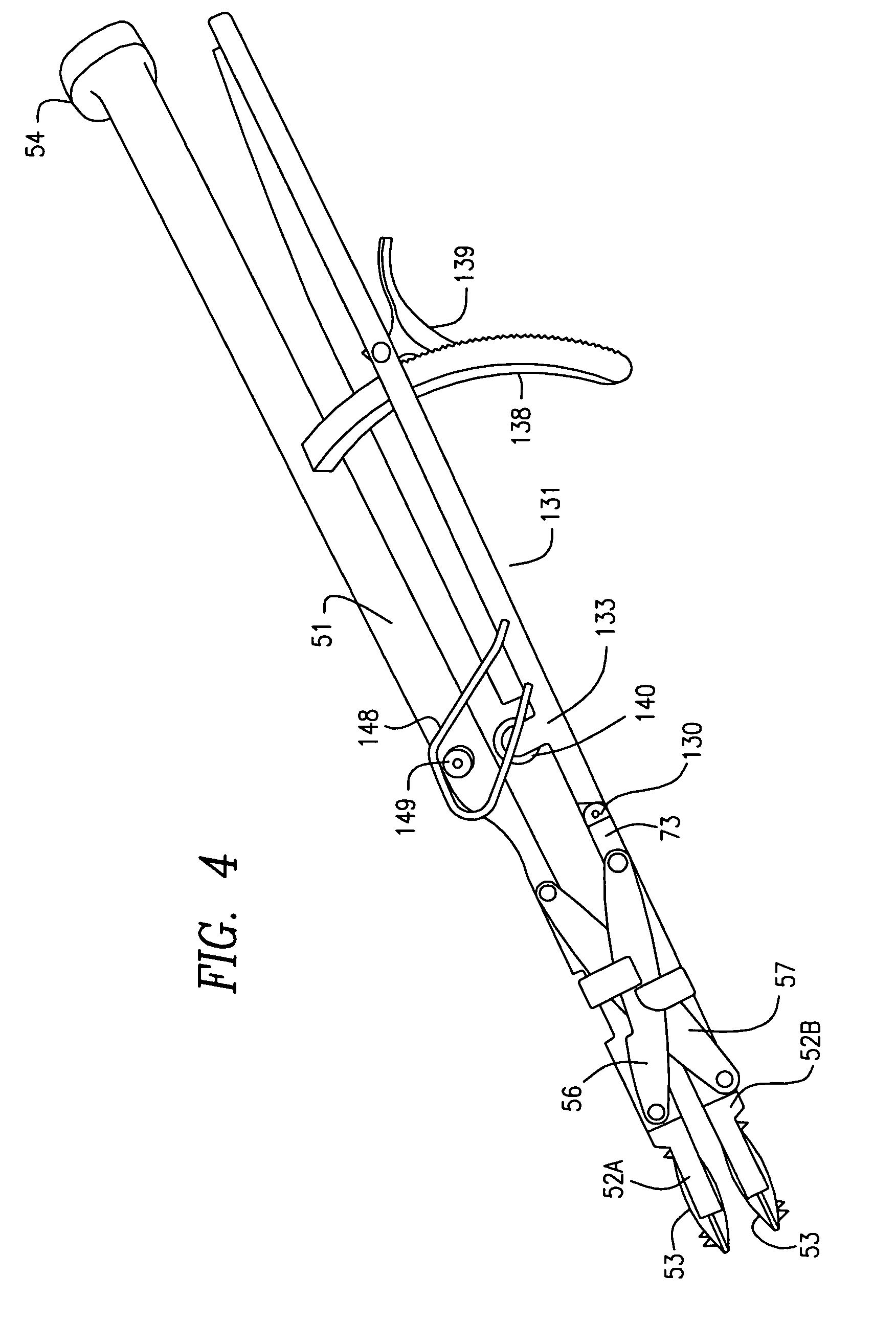
[0017]At the front end of the instrument body 51 there are two holders 52A and 52B for prosthesis plates 53. The prosthesis holders 52 are fork-shaped and open at the end. Their side branches form guides for the edge of the prosthesis plates 53. Their direction coincides with the longitudinal direction of the instrument body. This has the advantage that the operating surgeon is at all times aware of the orientation of the prosthesis plates, and that the force necessary for driving the prosthesis plates in can be exerted in the instrument direction. By overcoming a frictional force, the prosthesis plates can be inserted into the prosthesis holders 52, and made to slide out of said prosthesis holders 52, in the longitudinal direction of the instrument. At the rear end, the prosthesis body 51 has a strike plate 54. By striking this plate, the prosthesis plates 53 held by the prosthesis holders 52 can be driven in between two vertebral bodies when the prosthesis holders 52 are not sprea...


PUM


Abstract

Surgical instrument for inserting an intervertebral prosthesis, having first and second prosthesis holders (52A, 52B) for a pair of prosthesis plates, which holders are connected to one another by a parallel guide (57) and can be spread by a lever arrangement (131). The first of the prosthesis holders is arranged on an elongate instrument body in order to give the surgeon an exact picture of the orientation of the prosthesis and to allow force to be exerted in exactly this direction. The actuating lever (131) is articulated with its front end on the second prosthesis holder (52B) so as to pivot about a spindle (130) extending transversely with respect to the longitudinal direction of the instrument body (51) and to the direction of spreading. Behind this spindle (130), it has a limit stop (133) which acts directly or indirectly on the instrument body (51) or the first prosthesis holder (52A). The lever arrangement can also be the other way around.

Description

BACKGROUND OF THE INVENTION [0001]To insert intervertebral prostheses consisting of two prosthesis plates, each to be connected to a respective vertebral body, and of a prosthesis core arranged between these plates, insertion instruments are known (EP-A-333 990) which, at their front end, have two prosthesis holders which each receive a prosthesis plate. The prosthesis holders are connected to one another via a parallel guide which makes it possible initially to bring the prosthesis plates very close to one another, so as to be able more easily to introduce them into the narrow intervertebral space, and then to spread them apart with the adjoining vertebrae in order to be able to insert the prosthesis core between them. Thereafter, the prosthesis holders are moved back toward one another so that the prosthesis plates receive and securely hold the prosthesis core, and the instrument is removed. The known instrument is designed as a forceps which is angled in relation to the direction...

Claims


Application Information

Patent Timeline
IPC IPC(8): A61B17/60A61B17/56A61F2/44A61F2/46
CPCA61F2/4611A61F2/4425A61F2002/4615A61F2002/4687A61F2002/4623A61F2002/4628A61F2002/4622A61F2/4603
Inventor KELLER, ARNOLD
Owner DEPUY SPINE INC (US)
Why Eureka
Try Eureka