Prosthetic heart valves, scaffolding structures, and systems and methods for implantation of same

a heart valve and scaffolding technology, applied in the field of medical devices and methods, can solve the problems of increased risk of blood clot, inefficient blood circulation, and difficult recovery period of open heart surgery, and achieve the effects of preventing migration, enhancing sealing of support structures, and improving tissue adheren

Inactive Publication Date: 2010-08-31
AORTX
View PDF317 Cites 87 Cited by
  • Summary
  • Abstract
  • Description
  • Claims
  • Application Information

AI Technical Summary

Benefits of technology

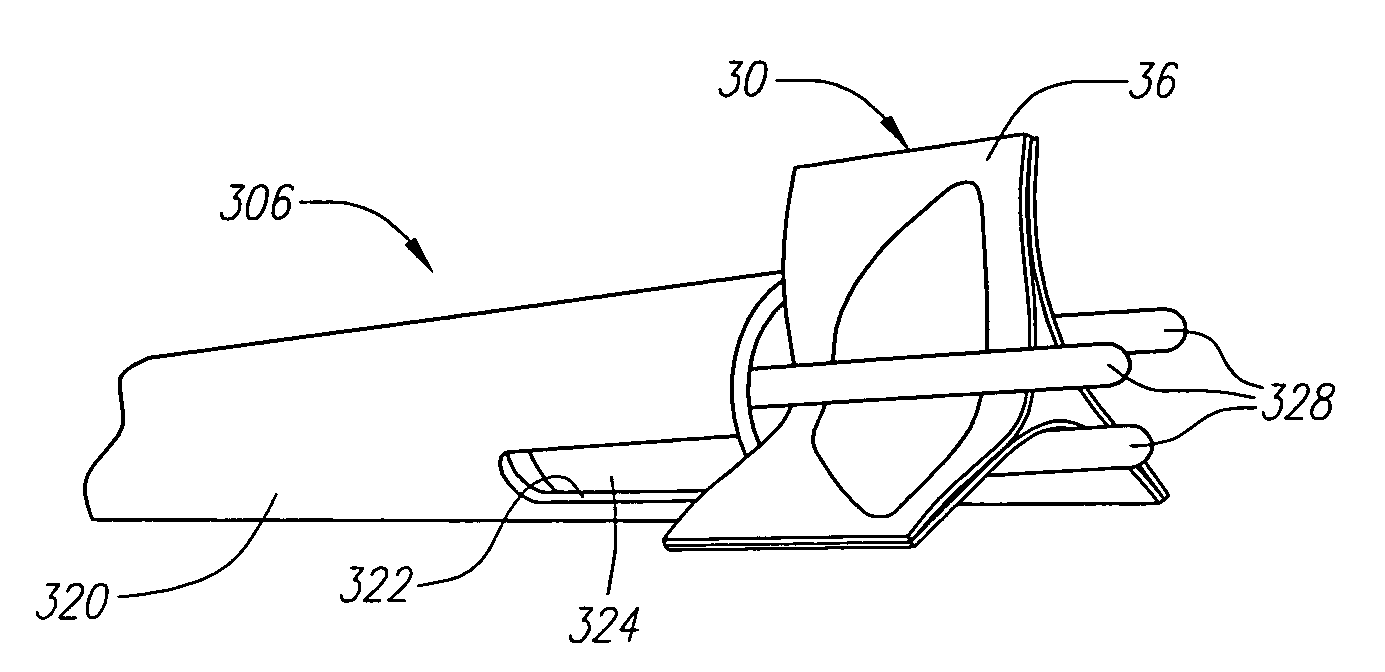
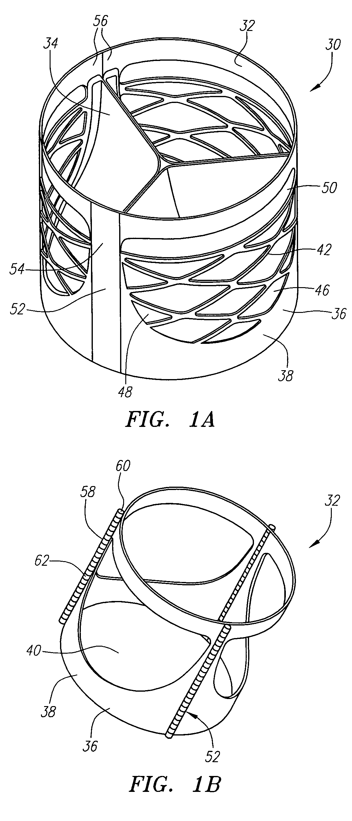
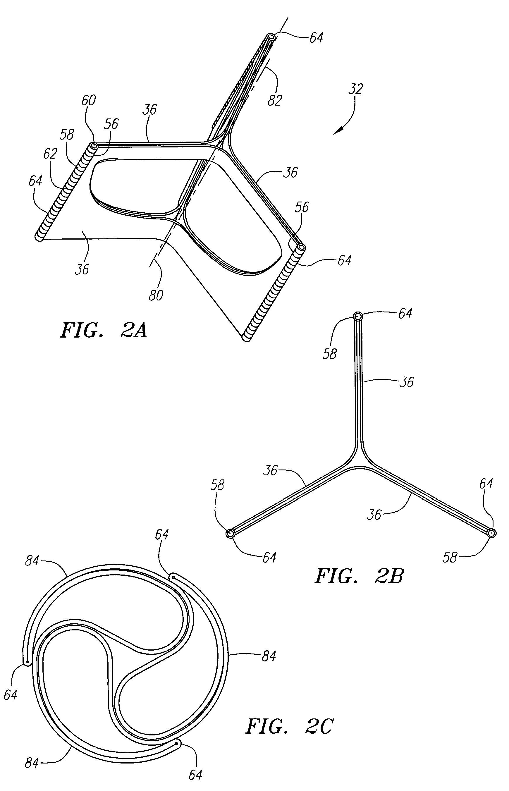
[0015]In one aspect of the invention, a prosthetic valve is provided. The prosthetic valve includes a support member and a valvular body attached to the support member. The prosthetic valve has an expanded state in which the support member has a cross-sectional shape that is generally cylindrical or generally oval and which has a first cross-sectional dimension (e.g., diameter), and a contracted state in which the support member has a second cross-sectional dimension (e.g., diameter) smaller than the first. The prosthetic valve is in its contracted state during delivery of the prosthetic valve to a treatment location, and in its expanded state after deployment at the treatment location. Preferably, the cross-sectional dimension of the support member in its expanded state is sufficiently large, and the support member possesses sufficient radial strength, to cause the support member to positively physically engage the internal surface of the body lumen, such as the aortic valve annulus or another biologically acceptable aortic position (e.g., a location in the ascending or descending aorta), thereby providing a strong friction fit.
[0052]In one embodiment, the expansion member comprises a plurality of inflation balloons oriented about a longitudinal axis. Each inflation balloon is connected at its proximal end by a feeder lumen to a central lumen that provides fluid communication between the inflation balloons and a source of inflation media associated with a handle portion of a catheter. The central lumen itself is provided with a guidewire lumen to allow passage of a guidewire through the expansion member. A flexible member is attached to the distal end of each of the inflation balloons, and also includes a guidewire lumen. In a preferred embodiment, the expansion member includes three inflation balloons, although fewer or more balloons are possible. The balloons may each be inflated individually, all together, or in any combination to obtain a desired force distribution. The multiple inflation balloon structure provides a number of advantages, including the ability to provide greater radial forces than a single balloon, and the ability to avoid occluding a vessel undergoing treatment and to allow blood or other fluid to flow through the device.

Problems solved by technology

Incompetence refers to valves that cause inefficient blood circulation by permitting backflow of blood in the heart.
The main problem with all mechanical valves is the increased risk of blood clotting.
Such open heart surgery is particularly invasive and involves a lengthy and difficult recovery period.
Although this type of design can provide for crimpability, it provides little radial stiffness.
The recoil is due in part because of the stiffness mismatches between the device and the anatomical environment in which it is placed.
These devices also commonly cause crushing, tearing, or other deformation to the valve leaflets during the contraction and expansion procedures.
This type of design provides high radial stiffness, yet crimping results in large material strains that can cause stress fractures and extremely large amounts of stored energy in the constrained state.
High stress states during crimping can reduce the fatigue life of the device.
These devices suffer from some of the same deficiencies as those described above.

Method used


Image

  • Prosthetic heart valves, scaffolding structures, and systems and methods for implantation of same
  • Prosthetic heart valves, scaffolding structures, and systems and methods for implantation of same
  • Prosthetic heart valves, scaffolding structures, and systems and methods for implantation of same

Examples


Embodiment Construction

[0120]Before the present invention is described, it is to be understood that this invention is not limited to particular embodiments described, as such may, of course, vary. It is also to be understood that the terminology used herein is for the purpose of describing particular embodiments only, and is not intended to be limiting, since the scope of the present invention will be limited only by the appended claims.

[0121]Unless defined otherwise, all technical and scientific terms used herein have the same meaning as commonly understood by one of ordinary skill in the art to which these inventions belong. Although any methods and materials similar or equivalent to those described herein can also be used in the practice or testing of the present invention, the preferred methods and materials are now described. All publications mentioned herein are incorporated herein by reference to disclose and describe the methods and / or materials in connection with which the publications are cited....


PUM


Abstract

Prosthetic valves and their component parts are described, as are prosthetic valve delivery devices and methods for their use. The prosthetic valves are particularly adapted for use in percutaneous aortic valve replacement procedures. The delivery devices are particularly adapted for use in minimally invasive surgical procedures.

Description

CROSS REFERENCE TO RELATED APPLICATIONS[0001]This application claims the benefit of U.S. Provisional Application Ser. No. 60 / 548,731, entitled “Foldable Stent for Minimally Invasive Surgery,” filed Feb. 27, 2004, and U.S. Provisional Application Ser. No. 60 / 559,199, entitled “Method and Multiple Balloon for Percutaneous Aortic Valve Implantation,” filed Apr. 1, 2004, each of which applications is hereby incorporated by reference in its entirety.FIELD OF THE INVENTION[0002]The present invention relates generally to medical devices and methods. More particularly, the present invention relates to prosthetic heart valves, structures for providing scaffolding of body lumens, and devices and methods for delivering and deploying these valves and structures.BACKGROUND OF THE INVENTION[0003]Diseases and other disorders of the heart valve affect the proper flow of blood from the heart. Two categories of heart valve disease are stenosis and incompetence. Stenosis refers to a failure of the val...

Claims


Application Information

Patent Timeline
Patent Type & Authority Patents(United States)
IPC IPC(8): A61M29/00A61F2/04A61F2/06A61F2/24
CPCA61F2/2418A61F2/243A61F2/2433A61F2/2439A61F2/2427A61F2/2436A61F2230/005A61F2220/0008A61F2220/0016A61F2220/0033A61F2220/005A61F2220/0091A61F2230/0013A61F2230/0091A61F2250/001A61F2250/006A61F2250/0063A61F2/9522
Inventor FORSTER, DAVID C.HENEVELD, SCOTTWALSH, BRANDONGINN, RICHARD
Owner AORTX
Why Eureka
Try Eureka