Stent deployment systems and methods

Inactive Publication Date: 2006-09-07
XTENT INC
View PDF64 Cites 72 Cited by
  • Summary
  • Abstract
  • Description
  • Claims
  • Application Information

AI Technical Summary

Benefits of technology

[0007] The present invention provides stent delivery catheters, systems and methods for deploying stents in body lumens. While the invention will have application in a number of different vessels in various parts of the body, the invention is particularly well-suited for stenting of the coronary arteries, saphenous veins and other grafts, and peripheral arteries including

Problems solved by technology

One drawback of PTCA has been the tendency in some cases for the coronary artery lumen to “restenose” following dilatation, wherein plaque reforms at the treatment site to narrow or block the lumen.
Even after stenting, however, some patients experience restenosis.
Current stents and stent deployment devices, however, are not well-suited to address these new potential applications for stents.
For example, current stents are designed for treating relatively short lesions, and often are not suitable for longer lesions through which the vessel may be curved, tapered or have other complex geometries.
Likew

Method used


Image

  • Stent deployment systems and methods
  • Stent deployment systems and methods
  • Stent deployment systems and methods

Examples


Embodiment Construction

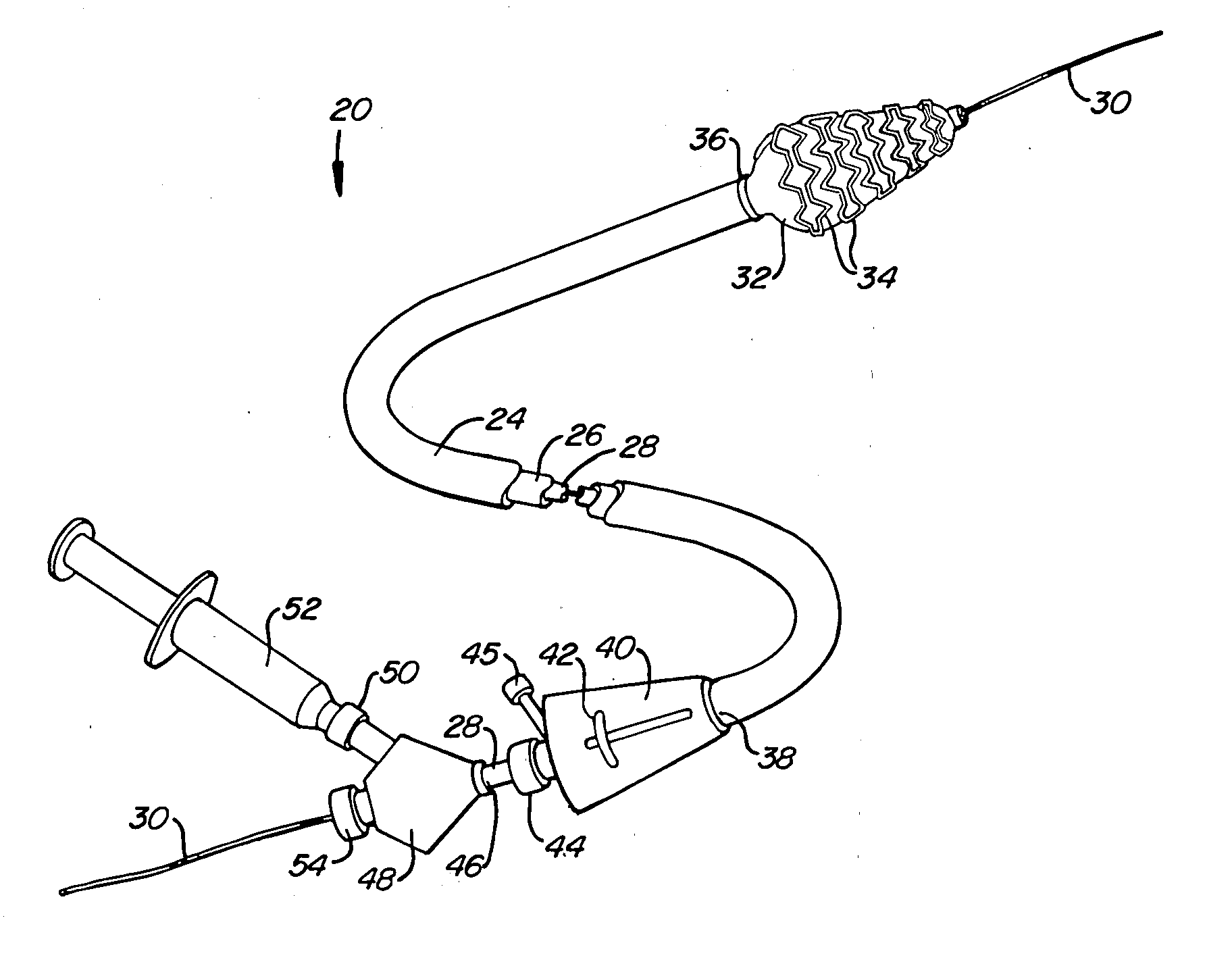
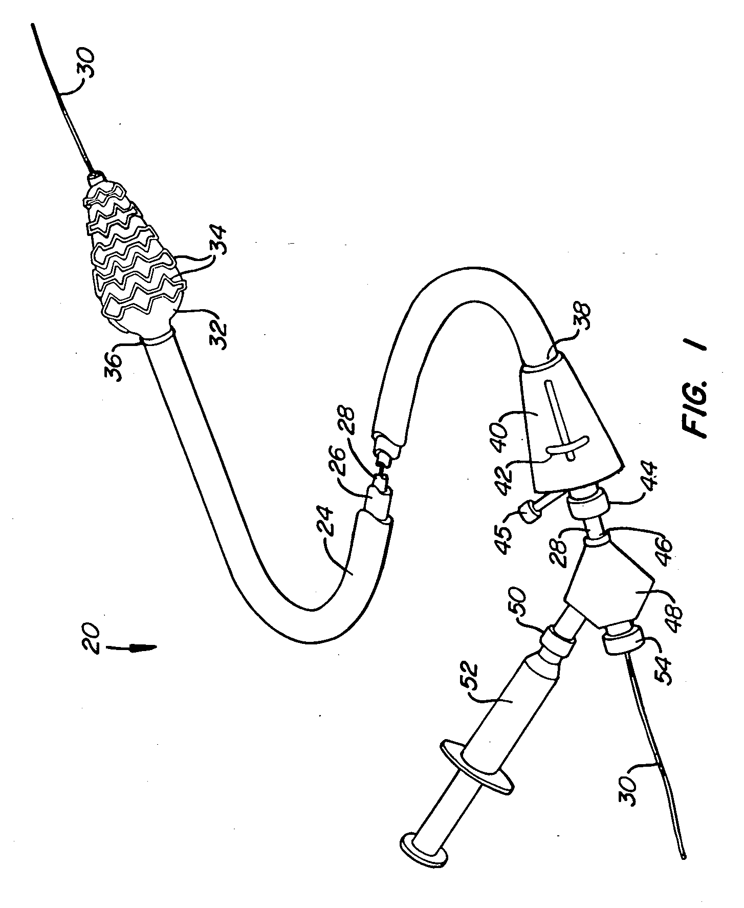
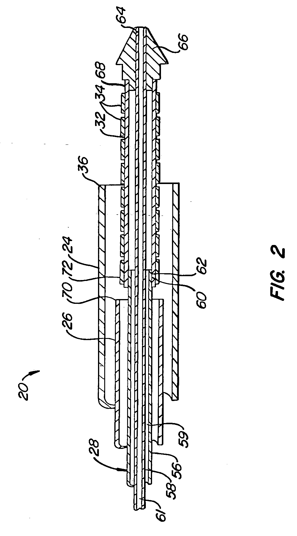
[0034] A preferred embodiment of a stent deployment system according to the invention is illustrated in FIG. 1. Stent deployment system 20 includes a sheath 24, a pusher tube 26 slidably disposed within sheath 24, and a catheter shaft 28 slidably disposed within pusher tube 26. Sheath 24, pusher tube 26 and catheter shaft 28 are all made of a flexible biocompatible material suitable for endovascular placement and positioning along a tortuous path from a peripheral vessel to the coronary arteries. A guidewire 30 is slidably positionable within catheter shaft 28 to facilitate introduction and tracking. An expandable member 32, which preferably is an elastomeric balloon, is mounted to the distal end of catheter shaft 28 and has an unexpanded shape suitable for endovascular positioning, and an expanded shape for deploying a stent within a vascular lumen. A series of tubular stent segments 34 are disposed about the periphery of expandable member 32 and are configured to be expanded by th...


PUM


Abstract

A stent deployment system includes a catheter shaft, an expandable member mounted to the catheter shaft, and one or more stents or stent segments slidably positioned on the expandable member. The stent deployment system is adapted for deployment of stents or stent segments in very long lesions and in tapered and curved vessels. The stent deployment system facilitates slidable movement of a stent in a distal direction relative to the expandable member while inhibiting slidable movement in a proximal direction relative to the expandable member.

Description

CROSS-REFERENCES TO RELATED APPLICATIONS [0001] This application is a divisional of U.S. patent application Ser. No. 10 / 458,062 (Attorney Docket No. 021629-001800US), filed Jun. 9, 2003, the full disclosure of which is incorporated herein by reference in its entirety.BACKGROUND OF THE INVENTION [0002] In coronary artery disease, stenotic plaques form within the coronary arteries, restricting and in some cases completely blocking blood flow to the heart muscle. In recent years, a number of different catheter-based interventions have been developed to treat coronary artery disease, including percutaneous transluminal coronary angioplasty (PTCA) and stenting. PTCA involves the placement of an endovascular catheter into the diseased coronary artery and expanding a balloon within the stenotic lesion to dilate the lumen, thereby improving blood flow through the treated area. One drawback of PTCA has been the tendency in some cases for the coronary artery lumen to “restenose” following dil...

Claims


Application Information

Patent Timeline
IPC IPC(8): A61F2/06A61F2/00A61F2/82
CPCA61F2/91A61F2/958A61F2002/826A61F2002/9583A61F2250/0039
Inventor ANDREAS, BERNARDSNOW, DAVID W.GRAINGER, JEFFRY J.
Owner XTENT INC
Why Eureka
Try Eureka