
Thermally pliable and carbon fiber stents

a carbon fiber and stent technology, applied in the field of stents, can solve the problem that the blood supply of the vessel cannot be increased, and achieve the effect of improving the blood supply of the vessel

Inactive Publication Date: 2006-03-07
AMIS JAMES PETER +1
View PDF9 Cites 67 Cited by
  • Summary
  • Abstract
  • Description
  • Claims
  • Application Information

AI Technical Summary

Benefits of technology

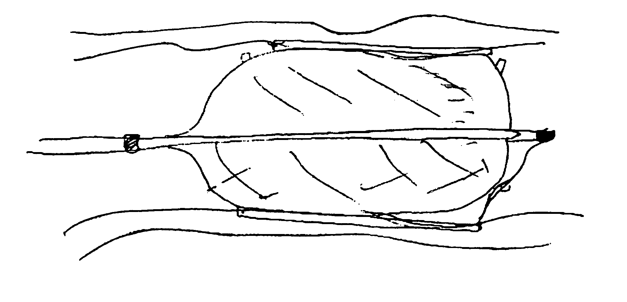
[0010]The prostheses of the present invention may also be used with therapeutic techniques on the hemodynamic field that include the use of stents for aortic coarctation, secondary aneurysm due to conventional balloon plasty being one of the principal indications. Use of a percutaneous stent in accordance with the present invention can be a fitting therapeutic option for patients who undergo coarctation of aortic angioplasty, develop aneurysm, and are later sent to surgery, with the procedure offering stability to the wall vessel and gradient disappearance. These inventive prosthesis applications are particularly suitable for use in supporting and holding back a dissected arterial lining which can occlude the fluid passageway therethrough.
[0012]An ideal stent in accordance with the present invention provides a number of mechanical characteristics. For example, it is desirable for the stent to have a small profile and high flexibility when in the contracted state to pass through narrow and tortuous passageways, but to have high radial strength over a range of expanded diameters, with little or no length change when deployed at the desired location. In some applications, such as deployment in the carotid arteries, it is also desirable for the stent to have a high degree of elasticity, so that if it is inadvertently compressed, the stent will re-expand to its originally implanted diameter.
[0014]To overcome the problems and limitations associated with stents having conventional radiopaque markers, it would be desirable to create the stent from a carbon fiber or similar material or compound, which preferably does not substantially limit the expansion capabilities of an expandable stent, and provide a means to assess stent length and diameter without obscuring the blood vessel lesion being repaired. Stents composed of carbon fibers are provided in several embodiments of the invention. An intravascular stent composed of carbon fiber or lactic acid polymers may be visualized with magnetic resonance imaging (MRI), fluoroscopy, or any other imaging technique. The stent can be easily imaged during the follow-up of the patient, in order to determine the stability of the location of the stent.
[0016]The present invention has for a purpose to provide a radially expansible and contractile prosthesis whereby drawbacks of known techniques are attenuated or avoided.
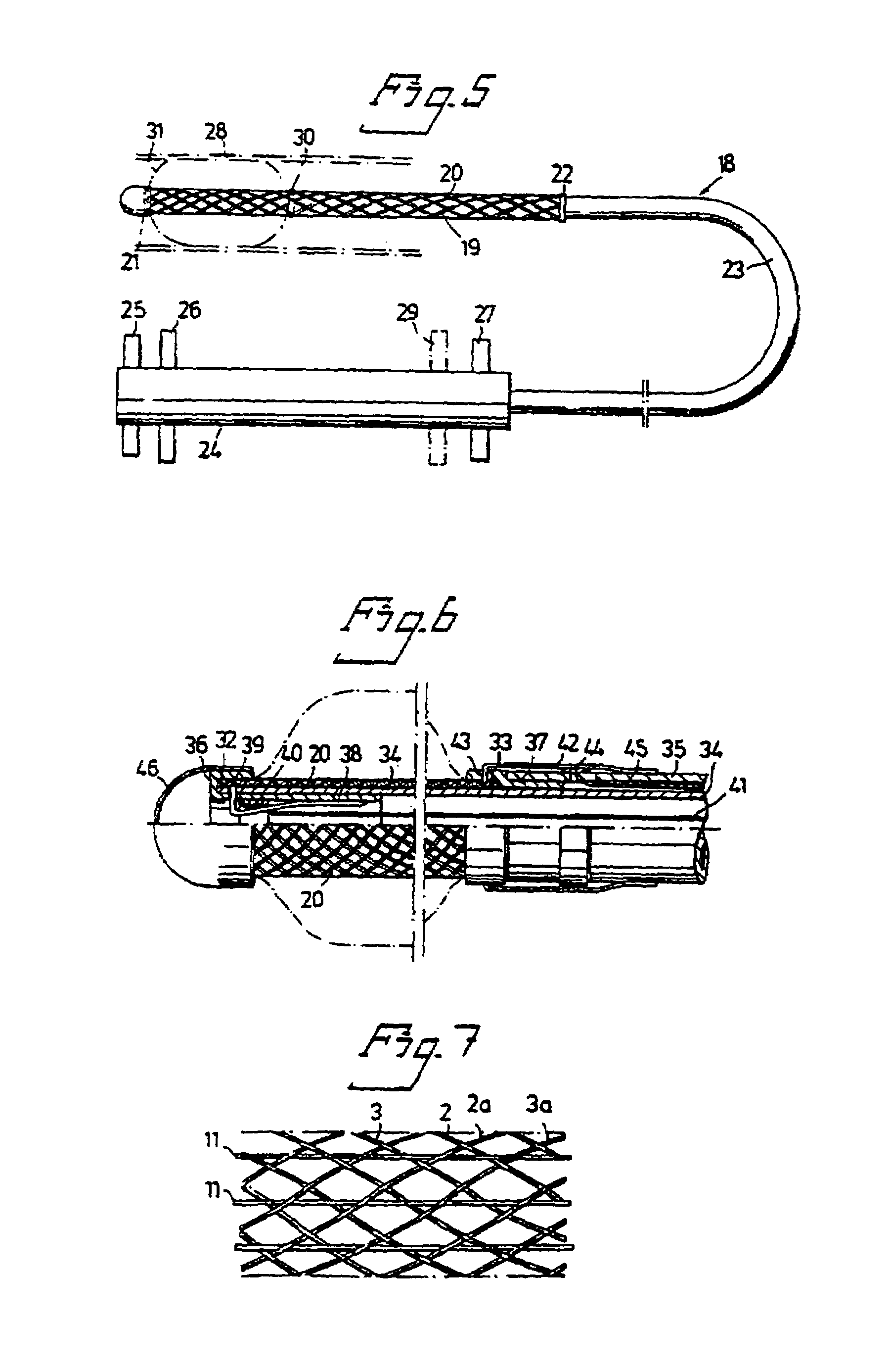
[0018]In accordance with one embodiment of the present invention there is provided an instrument for the deployment or retraction of a self-expanding braided stent in a body canal, which comprises an elongated tubular outer sleeve having a proximal end and a distal end, an elongated core disposed within the sleeve and movable relative to the sleeve, the core being longer than the sleeve and having a proximal end and a distal end and including a grip member at or near the distal end of the core, the grip member being an integral portion of the core or a sleeve or coating attached around the periphery of the core and being adapted to: (i) releasably hold a self-expanding stent within the outer sleeve, there being sufficient clearance between the grip member and the outer sleeve to accommodate the stent without distortion, (ii) deploy the stent beyond the distal end of the outer sleeve when the outer sleeve is moved in a backward direction relative to the core and (iii) retract the stent back within the outer sleeve when the core is pulled in a backward direction relative to the outer sleeve.

Problems solved by technology

In occlusive vascular disease, such as arteriosclerosis, plaque accumulates within a vessel and gradually narrows the vessel to a degree that the vessel can no longer supply an adequate flow of blood.

Method used


Image

  • Thermally pliable and carbon fiber stents
  • Thermally pliable and carbon fiber stents
  • Thermally pliable and carbon fiber stents

Examples


Embodiment Construction

[0051]The following disclosure references figures from U.S. Pat. No. 4,655,771, which patent is incorporated herein in its entirety by reference.

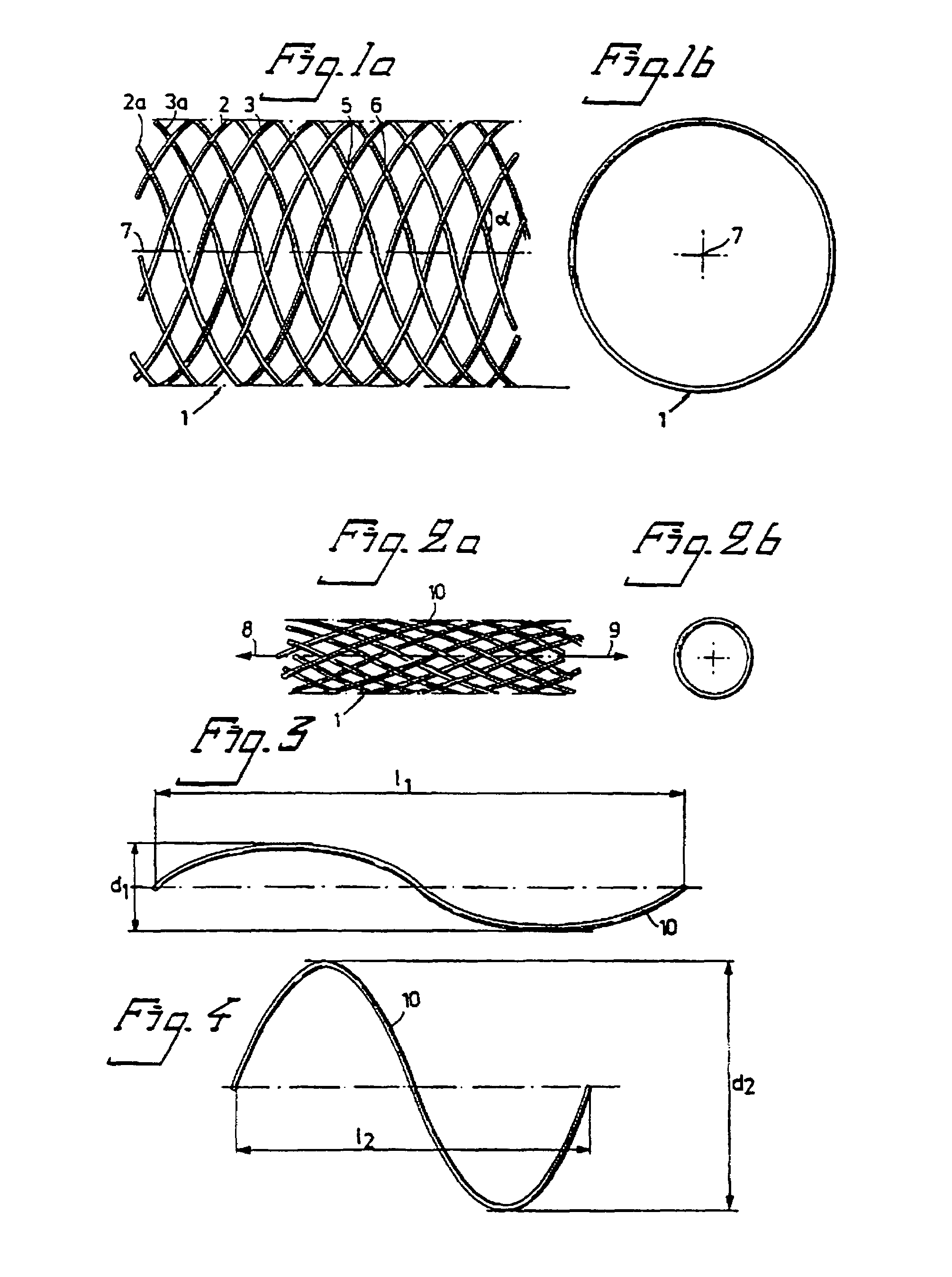
[0052]A flexible tubular body according to the present invention has been found to be suited for use as a prosthesis for transluminal implantation in blood vessels or other similar organs of the living body. The tubular body is inserted into place in the organism in a contracted state, i.e. with reduced diameter. After the tubular body has been inserted into position it is subjected to expansion and can stay in place in an expanded state by self-fixation if the diameter of the body in unloaded condition is selected somewhat larger than the diameter of the surrounding wall. This construction results in a certain permanent pressure of engagement against the inner wall so as to ensure good fixation.

[0053]To obtain the desired function the axially directed angle between crossing elements cam be greater than about 60 degrees, and can in some emb...


PUM


Abstract

A prosthesis for insertion into a body passage is disclosed. The prosthesis includes a plastic or polymer base material which is compatible with living tissue and which possesses a memory of a predetermined configuration. The base material further has a glass transition temperature at which the prosthesis can be molded intravascularly from the predetermined configuration to a larger-radius implant configuration, which is sized and shaped to conform to an internal anatomy of the body passage to expand a narrow segment of or to occlude an opening of an out pouch of the body passage. The glass transition temperature is greater than a temperature of the body passage so that the prosthesis after being molded can be allowed to cool to the temperature of the body passage.

Description

[0001]This application claims the benefit of U.S. Provisional Application No. 60 / 313,284, filed Aug. 17, 2001, the entire contents of which are incorporated herein by reference.BACKGROUND OF THE INVENTION[0002]1. Field of the Invention[0003]The present invention relates generally to medical devices and, more particularly, stents.[0004]2. Description of Related Art[0005]In recent years a number of minimally invasive techniques have been developed to treat occlusive vascular disease, and to repair aneurysms occurring in the circulatory system, vessels, and other organs. In occlusive vascular disease, such as arteriosclerosis, plaque accumulates within a vessel and gradually narrows the vessel to a degree that the vessel can no longer supply an adequate flow of blood. A number of vascular prostheses have been developed to re-expand and retain the patency of such afflicted vessels, for example, after atherectomy or angioplasty.SUMMARY OF THE INVENTION[0006]Prostheses are disclosed which...

Claims


Application Information

Patent Timeline
Patent Type & Authority Patents(United States)
IPC IPC(8): A61F2/06A61F2/90
CPCA61F2/90A61F2/958A61F2220/0008A61F2002/9665A61F2250/0039A61F2/966
Inventor AMIS, JAMES PETERU, HOI SANG
Owner AMIS JAMES PETER
Learn More