Material separator

a separator and material technology, applied in the direction of liquid degasification, separation process, liquid displacement, etc., can solve the problems of equipment beyond repair, costly and extensive cleaning operations of piping and equipment, equipment damage or plugged up, etc., to slow the fluid velocity and quick and efficient removal

Inactive Publication Date: 2012-11-13
EXPRESS ENERGY SERVICES OPERATING LP
View PDF16 Cites 27 Cited by
  • Summary
  • Abstract
  • Description
  • Claims
  • Application Information

AI Technical Summary

Benefits of technology

[0008]The current invention uses the naturally occurring gravitational separation of gases, fluids and solids in a manner that allows the materials to be quickly and efficiently removed from the system. By using this natural gravitational separation the assembly can be much smaller and much more efficient than any of the systems currently in operation. Under the current invention the separator is oriented at an angle to allow the materials which may include gas, fluid, and particulate materials to enter into the assembly on the high side of the assembly and travel along the length of the assembly. This orientation allows the gas to naturally separate from the liquid and sand. This also allows the gas to stay separated while traveling along the entire length of the assembly. Although the gas may travel at a higher velocity than the fluid this separation allows it to travel without affecting either the liquid or the sand velocity. The faster gas travels along the top side of the assembly whereas the fluid travels under that and the heavy particles under that. What this means is that the sand which falls faster through gas moves to the lower portion of the assembly quicker with gas than it does even with fluid. This means that even under higher flow rates the sand is not adversely affected by the velocity of the gas. This affect is further accentuated by the use of velocity shields that are oriented vertically along the bottom portion of the assembly. These shields help to further slow the fluid velocity along the lower portion of the assembly letting the sand fall back to the bottom while being protected from the effect of the higher gas and fluid velocities along the top side of the assembly.
[0009]In other words the natural gravitational effect on the fluid and the sand let the sand fall to the low side of the assembly. This means that the sand does not have to fall through the fluid column that is traveling in the opposite direction from the particles decent. The sand need only transport to the lower wall of the separator. This significantly reduces the amount of time that it takes for the sand particle to reach the bottom of the assembly. In relationship to a vertical column where the sand is falling at a rate of 20 ft. per minute and the fluid might be lifting the sand at a rate of 17 ft. per minute the net rate of settling is 3 ft. per minute this means that on a 15 ft. vertical column it will take the sand 5 minutes to reach to bottom. In this invention at the same settling rate the sand will reach the low side of the separator in approximately 1.9 seconds. This allows the sand to not only be removed from the assembly faster but means that there is less sand entrained in the fluid for any moment in time. This improved efficiency based on time and settling rates allows the assembly to handle much higher volumes of fluids and sand using a smaller diameter than the other systems. This lower weight and size is important when it comes to handling and transport of the assembly. The larger vertical columns had to be laid down and transported to location because of their great size. In this embodiment of the invention once the sand has reached the low side of the assembly the velocity shields protect the sand from the gas and fluid flow. The velocity shields provided sufficient clearance between them and the wall of the assembly as to allow the sand enough room to slide down into the collection chamber at the lowest point in the interior of the assembly. Once the accumulated sand has reached the collection chamber it can then be dumped or purged from the system to a holding tank or pit.

Problems solved by technology

In addition some of the equipment can become damaged or plugged up when the sand settles out inside of the equipment piping or pipe lines.
This sand can also damage the equipment beyond repair or can result in costly and extensive cleaning operations to the piping and equipment.
The problem with this technology is, for the system to work the fluid has to be accelerated and directed to a flow path that causes a swirling affect that then slings the sand particles to the outside of the flow path.
These materials although resistant do not stop the abrasion and only prolong the wear.
Once however the components have been worn beyond their design tolerances they lose their effectiveness and the separators cease to work.
This failure can be unpredictable and catastrophic.
With new drilling technologies the current flow rates and pressures make this method of separation undesirable.
The problem with this technology is the higher the flow rate is, the larger the settling pot has to be for separation to occur.
Therefore these types of separators although robust are not very efficient with higher flow rates and smaller sand particles.
The other problem is when using a settling pot, as the pressure increases so does the wall thickness of these pots.
Some of these pots are so large that they are difficult to transport and set up and to work on.
This acceleration of gas and fluid caused by high gas flow rates make these separators ineffective in removing contaminates from the fluids.
This device is somewhat effective in separating heavier sand particles in a liquid stream with no gas however it would not be as effective is separating out finer sand particles and in situations where gas is present in fluid.
This use of convection is slow and not very efficient.
This method also generates turbulence within the fluid flow or rotation caused by the convection reducing the effectiveness of the gravitational separation.
An indication that this design does not work well with smaller size particles of sand is that in some of the disclosed embodiments a sand filter is used to separate the smaller medium from the fluid mixtures.

Method used


Image

  • Material separator
  • Material separator
  • Material separator

Examples


Embodiment Construction

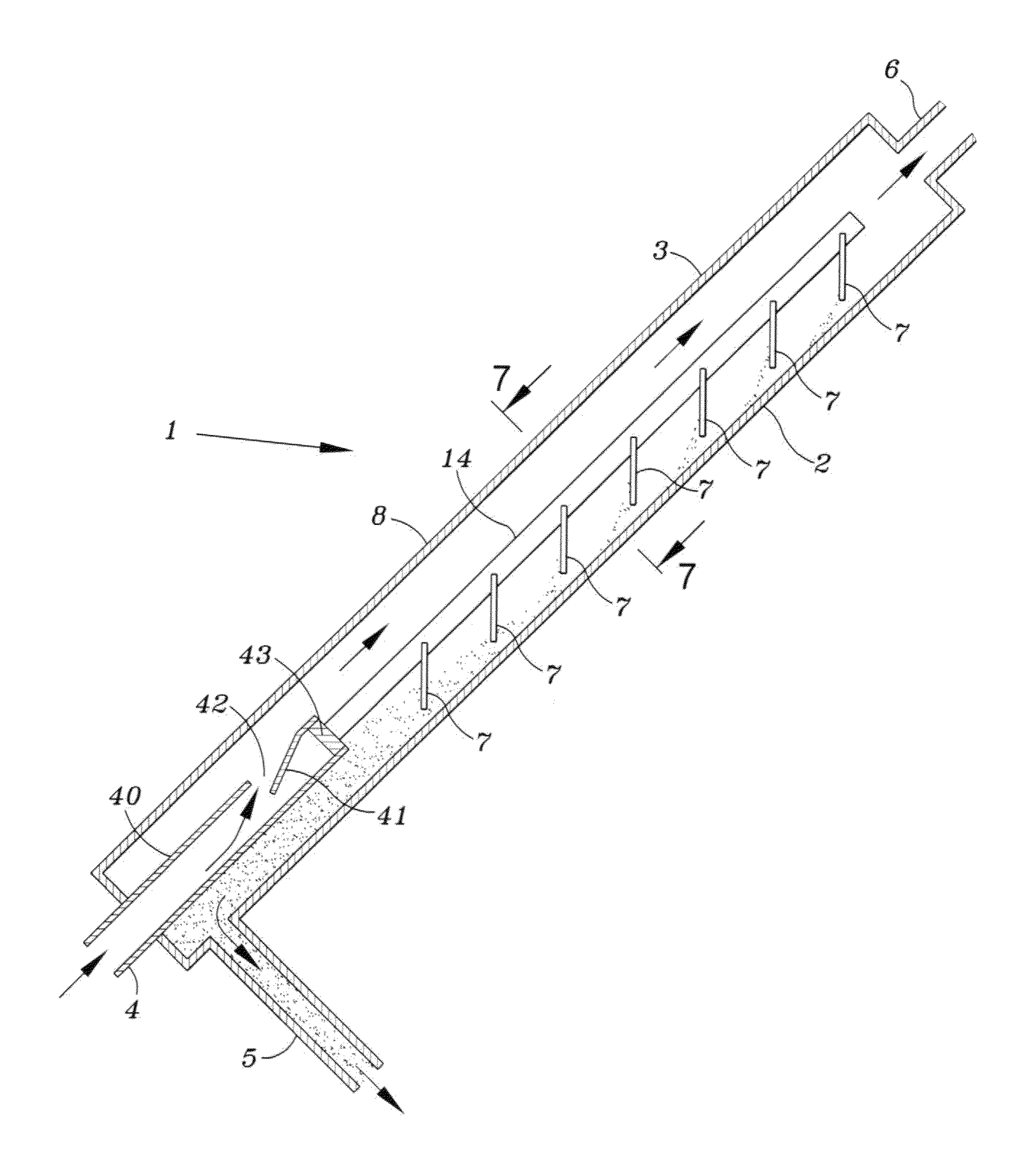
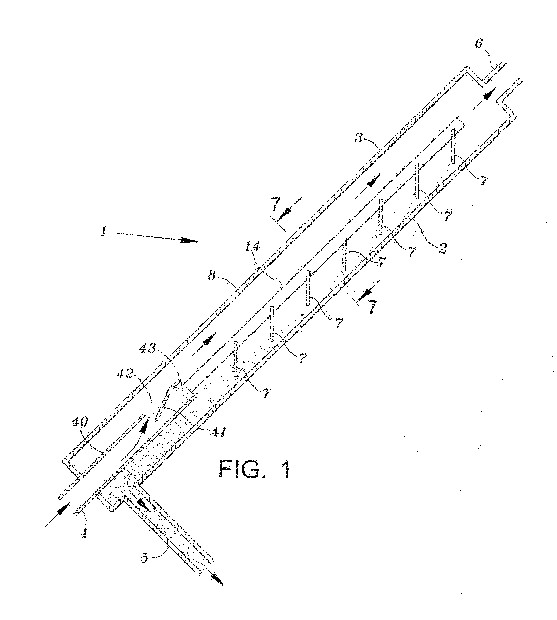
[0018]FIG. 1 illustrates an embodiment of the invention and shows a view of a separator 1. A plurality of separators may be connected to common manifolds for the input fluid, particle removal, and for the output fluid. The separator includes a first elongated body portion 8 having an upper side wall 3 and a lower side wall 2. In use the separator is inclined with respect to the horizontal at an angle of about, but not limited to, twenty to seventy degrees.

[0019]The separator body 8 may be a cylindrical tube having an inlet 4 at the lower portion, an outlet 5 in the lower portion for removal of the separated material, for example sand, and an outlet 6 in an upper portion for the liquid and any gas that may be present in the fluid introduced at the bottom of the body.

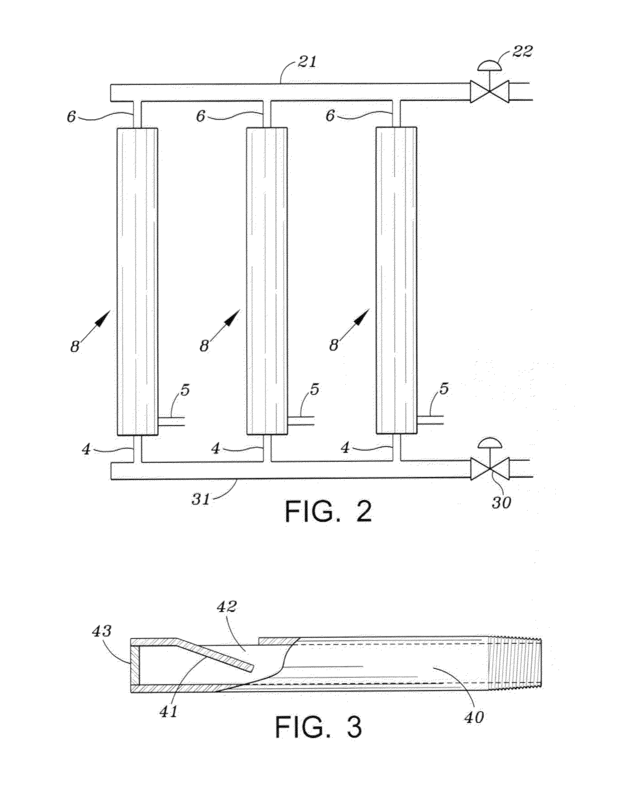
[0020]A cylindrical pipe 40 is connected to the inlet 4 and is secured within the body 8. As shown in FIGS. 3 and 5, the wall of the pipe has an outlet 42 formed by cutting a U-shaped slot in the wall and then bending the...


PUM

PropertyMeasurementUnit
angleaaaaaaaaaa
angleaaaaaaaaaa
velocityaaaaaaaaaa

Abstract

A material separator removes material such as sand from a fluid utilizing an inclined housing having a fluid flow inlet in a lower portion of the housing. Higher density material descends by gravity to a lower wall of the inclined housing and continues to travel down the lower wall portion to a lower section of the housing where it is removed. The remaining fluid which may contain a liquid and a gas is removed from the housing via an outlet at the upper portion of the housing.

Description

BACKGROUND OF THE INVENTION[0001]1. Field of Invention[0002]This invention is directed to a device for separating materials of different density, from a flowing stream of fluid which may contain solids, liquids and gases. The device may be readily transported to remote locations such as oil or gas wells to remove solids, for example sand, from fluid that is used at the well site for various purposes and requires treatment after use.[0003]2. Description of Related Art[0004]Currently sand separation equipment is used following fracturing or well stimulation operations. The sand separators are placed in line in front of the choke manifold and other production piping or equipment. This is done in an effort to avoid erosive damage that can be caused by the sand flowing at high velocities through the equipment. In addition some of the equipment can become damaged or plugged up when the sand settles out inside of the equipment piping or pipe lines. This sand can also damage the equipment b...

Claims


Application Information

Patent Timeline
Patent Type & Authority Patents(United States)
IPC IPC(8): B01D21/00B01D45/02
CPCB01D21/0045B01D21/0057B01D45/02B01D2221/04
Inventor NOLES, JR., JERRY W.
Owner EXPRESS ENERGY SERVICES OPERATING LP
Why Eureka
Try Eureka