Multi-configurable tractor

a tractor and multi-configurable technology, applied in the field oftractors, can solve the problems of requiring relatively expensive implements and equipments, and reducing the service life of the tractor, so as to achieve the effect of improving the service life, reducing the cost of equipment, and improving the service li

Inactive Publication Date: 2005-09-01
WHITE TRUST THE DEBRA ARLENE GLAD
View PDF15 Cites 29 Cited by
  • Summary
  • Abstract
  • Description
  • Claims
  • Application Information

AI Technical Summary

Benefits of technology

[0012] An agricultural tractor incorporates a steel tube frame having telescoping members to accommodate changes in length and, hence, the wheel base. Steel tubes with telescoping members support the front wheels. Steel tubes with telescoping members house telescoping axles supporting the rear wheels. Thereby, the length and width of the tractor may be modified without disturbing attachments to the frame or to the axles. All attachments to the frame, including motor and transmission mounts, tillage implements, hitches or brackets, are secured to the frame by means of clamping devices. Several implements may be attached to the full length of the frame as space allows and repositioned at will to accomplish multiple tillage processes during one pass through a field. Likewise, the drive train components, such as engine, transmission, hydraulic drive, etc., can be added, removed, replaced or repositioned without destroying the integrity of the frame. The steel tube frame is positioned at an elevation with sufficient ground clearance to permit implements to be mounted beneath the tractor and forward of the operator for better visibility. Placing an implement closer to the front axle makes it possible to till close to a field perimeter and permit smaller turns. The front wheel clearance in combination with the geometry of the steering mechanism permit turning the tractor about the center of either rear wheel or about any pivot point located on the axis of rotation of the rear wheels while providing a true turning radius for each of the wheels and thereby eliminate wheel plowing. By telescopic movement of the frame, the wheel width and wheel base may be adjusted to provide increased stability and permit use of wide tillage implements to create a more favorable distance between compacted wheel paths in a controlled traffic culture.
[0013] It is therefore a primary object of the present invention to provide a tractor having easily variable wheel width and wheel base.
[0016] Another object of the present invention is to provide a true turning radius for each of the wheels to eliminate plowing of any of the wheels.
[0020] Still another object of the present invention is to provide sufficient clearance for use of large diameter front wheels for steering while maintaining a true turning radius.
[0022] Yet another object of the present invention is to provide an adjustable width between the front and rear wheels to increase the width between soil compaction.
[0025] A yet further object of the present invention is to provide a method for preventing plowing of any of the wheels during a turn of any radius.

Problems solved by technology

For the most part, these tractors are capable of performing the various operations required by a farmer but any reconfiguration, to the extent possible, requires relatively expensive implements and equipments available only from the manufacturer of the tractor.
The wheel width of conventional tractors is limited to the length of the associated fixed axles and the width of the tractor is fixed which creates burdens during transport of large tractors.
The wheel hubs are fastened to a fixed axle and changing wheel centers is both time consuming and labor intensive.
The front axle rocks on a center pin only which renders it impossible to raise one or the other front wheels to roll over obstacles or increase the weight on one or the other of the front wheels.
The frame length of a tractor is fixed and by increasing the wheel width without lengthening the wheel base, crabbing results and some stability is lost.
Because of the lack of uniformity of tractors from different manufacturers, equipment to be suspended beneath the tractor from the frame requires that each such piece of equipment be specifically designed for a particular tractor due to both the configuration of the frame and the often minimal ground clearance.
Sometimes it is beneficial to add weight for traction and such weight must be added manually to a conventional tractor which is labor intensive and hard work.
Conventional tractors provide traffic lanes of a two row width, which is an unavoidable limitation of the width of the root zone between the compacted traffic lanes.
That is, the compacted traffic lanes create root barriers and reduce the yield.
Thus, attachment of toolbars is generally restricted to front or rear fixed points.
The power train components are unique to the configuration of the monolithic design and any repair or replacement requires expensive components available primarily only from the manufacturer of the tractor.
Because of limited clearance between the front wheels and the frame of a conventional tractor, the turning radius is limited.
With such limitations and the geometry of conventional steering apparatus, the front wheels tend to plow in a turn and a true turning radius for each of the front wheels is not possible.
Moreover, as the front wheels turn about a different point, one or both of the rear wheels may tend to plow or skid.
Toolbars are conventionally mounted at the rear of a tractor, which renders it difficult for an operator to visually monitor the toolbar and operation of the attached equipment.
This often causes the tractor to drift sideways.
The size of the tires used with conventional tractors generally cannot be changed.
In the latter case, a much wider area is compacted to the detriment of crop yield.
Usually, an auxiliary axle cannot be added to a conventional tractor to increase traction.

Method used


Image

  • Multi-configurable tractor
  • Multi-configurable tractor
  • Multi-configurable tractor

Examples


Embodiment Construction

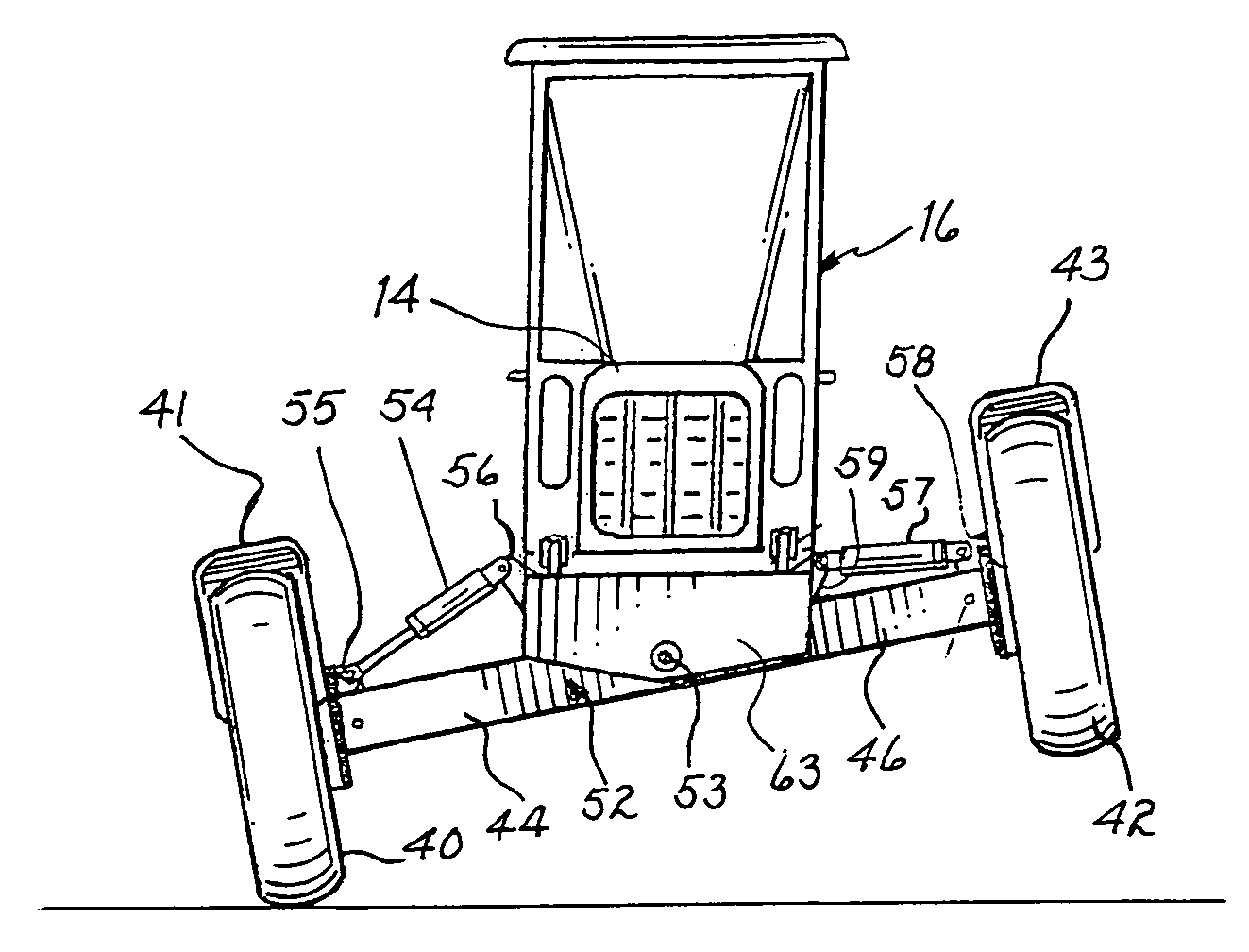
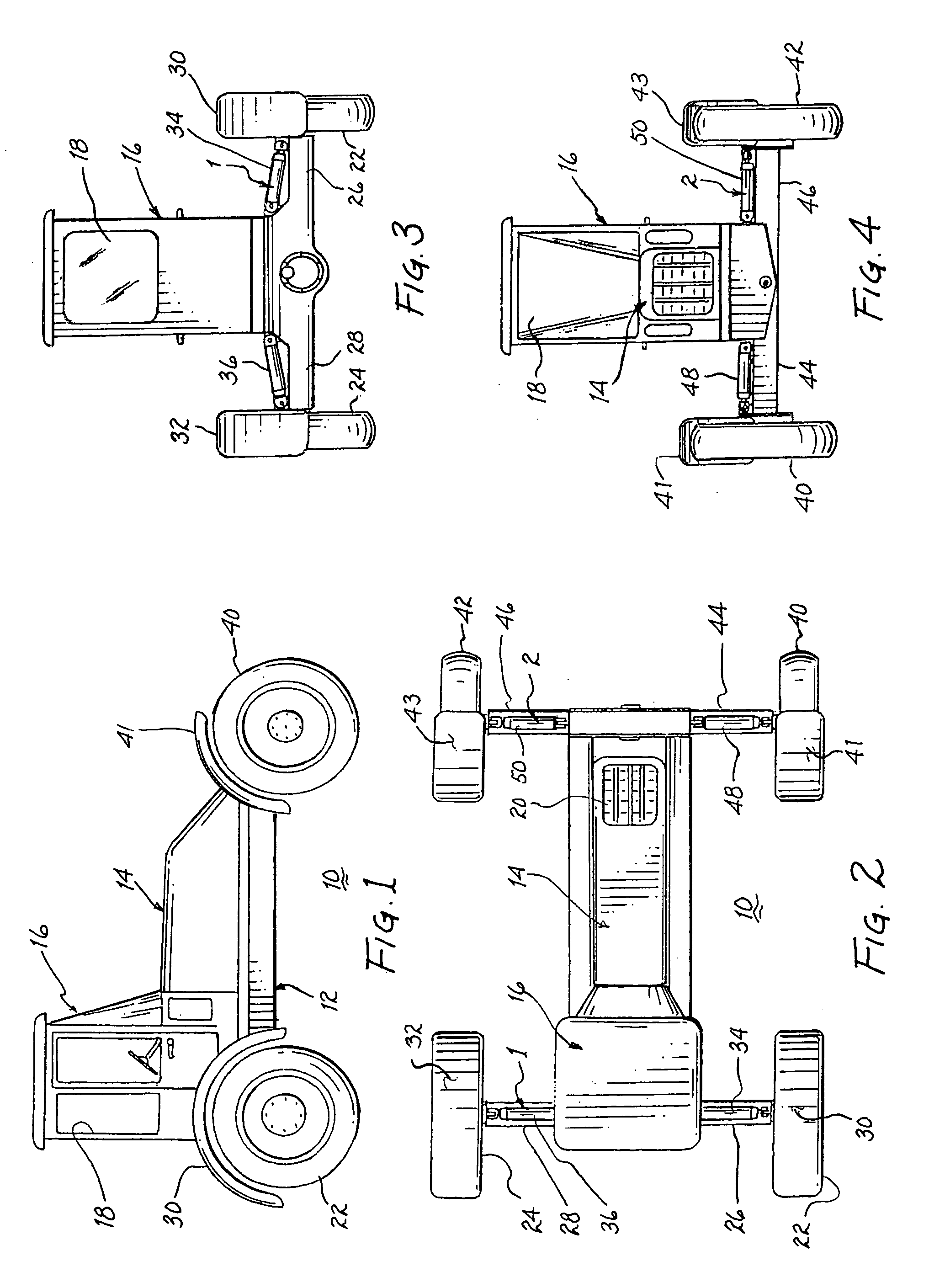
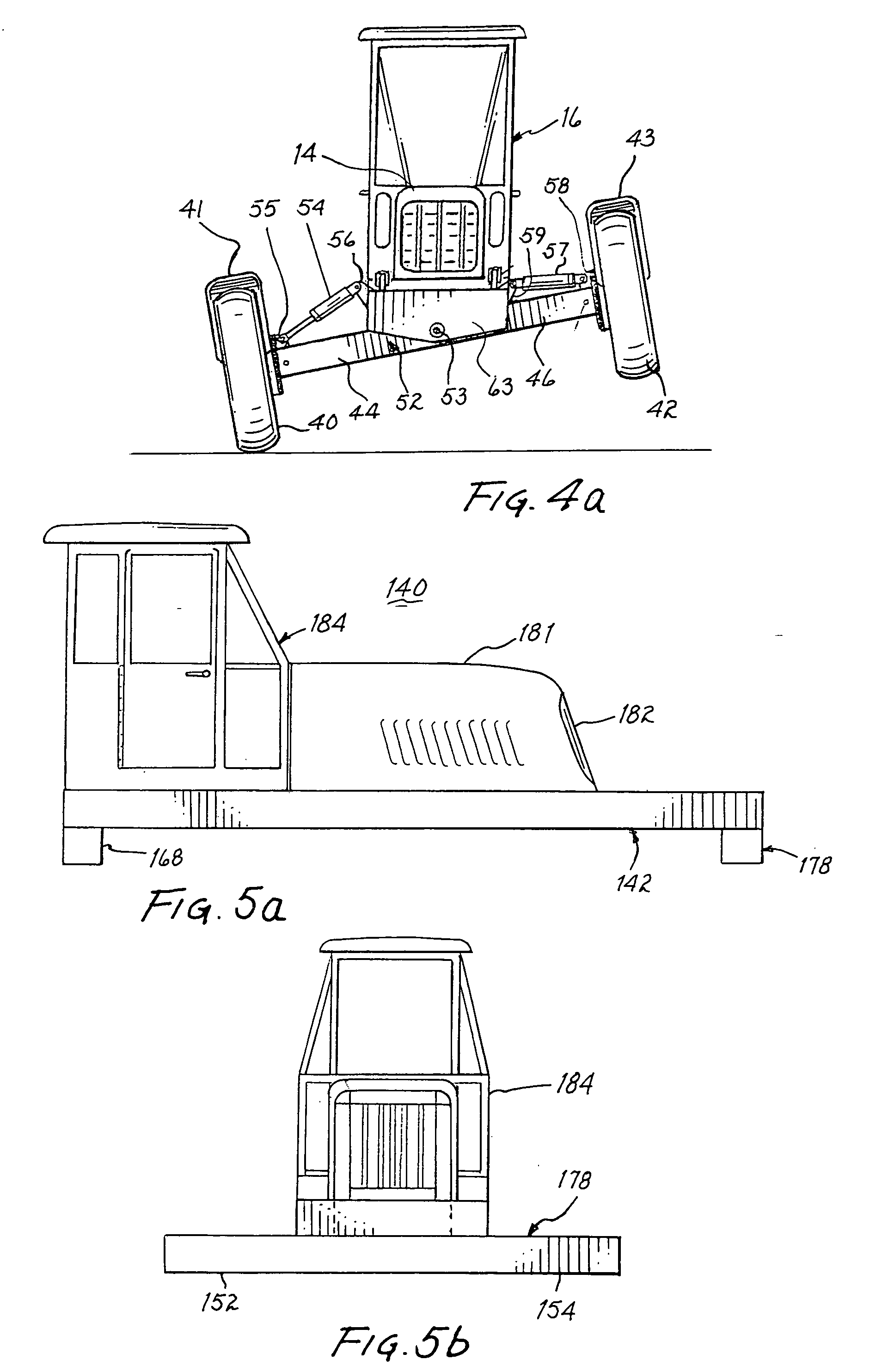
[0056] Referring to FIGS. 1, 2, 3 and 4 there is shown an agricultural tractor 10 embodying the present invention. The chassis of the tractor is formed of a tubular steel frame 12 upon which are mounted the conventional motor, transmission, steering mechanism and various ancillary components. A hood 14 shields the motor and its various components. A cab 16 encloses the operator and includes a plurality of windows 18 to provide visibility forward, backward and to the sides. Hood 14 may include a grill 20 or the like to provide cooling air to the motor within the hood. Rear wheels 22, 24 are supported by respective telescoping axles enclosed within telescoping steel tubes 26, 28, respectively. Fenders 30, 32 may be mounted above the rear wheels to prevent splatter of mud and the like. Extension and contraction of telescoping tubes within tubes 26, 28 is controlled by hydraulic rams 34, 36. Front wheels 40, 42 are pivotally mounted and coupled with a steering mechanism, as will be desc...


PUM


Abstract

A tractor includes a motor, transmission, drive shaft and rear differential for driving the rear axles mounted on a main tubular frame of a variable configuration. Forwardly extendable telescoping tubular frame members are actuated by respective rams to selectively increase the wheel base between the front and rear wheels. The front and rear telescoping tubes supporting each of the wheels are selectively extendable to significantly increase the wheel width of the tractor; the axles for the rear wheels are commensurately extendable. A toolbar dependingly supported from the main frame in front of the cab permits the operator to view the operation of attached implements while driving. The toolbar may include a row guide causing the toolbar to move laterally as necessary to follow a row and the toolbar is connected to the steering mechanism to control the direction of travel of the tractor. The front wheels are pivotally mounted on the corresponding telescoping tubes to provide sufficient clearance to permit near 180° pivotal movement. The steering mechanism is capable of pivoting each front wheel through an angle of about 180° and establishes an appropriate geometric relationship between the front wheels to permit the tractor to turn about any center of rotation intersected by the common axis of rotation of the rear axle, including pivoting about either rear wheel, while maintaining the axis of rotation of each front wheel in intercepting relationship with the center of rotation. Moreover, the turn radius at the end of a row is minimal and can be further reduced by temporarily reducing the length of the frame. Various implements, including a toolbar, can be readily attached directly to the tubular frame at any location intermediate the front and rear axles, as necessary.

Description

CROSS-REFERENCE TO RELATED APPLICATIONS [0001] The present application is related to and claims priority of a provisional application entitled “DIRECTIONAL CONTROL FOR A TRACTOR”, filed Feb. 11, 2004, and assigned Ser. No. 60 / 543,980 and directed to an invention made by the present inventor.BACKGROUND OF THE INVENTION [0002] 1. Field of the Invention [0003] The present invention relates to tractors for use in farming operations and, more particularly, to tractors readily configurable to meet multiple unique operational requirements and to obtain the benefits therefrom. [0004] 2. Description of Related Prior Art [0005] Conventional tractors of greater or lesser size have been used by farmers for decades to pull various implements and to perform various conventional farming operations. For the most part, these tractors are capable of performing the various operations required by a farmer but any reconfiguration, to the extent possible, requires relatively expensive implements and equi...

Claims


Application Information

Patent Timeline
Patent Type & Authority Applications(United States)
IPC IPC(8): B60G9/02B62D49/06B62D49/08
CPCB60G9/02B60G2200/322B60G2200/44B60G2300/082B62D49/08B60G2800/0194B60G2800/912B62D49/0657B62D49/0678B60G2300/40
Inventor WHITE, ROBERT E.
Owner WHITE TRUST THE DEBRA ARLENE GLAD
Why Eureka
Try Eureka