

Apparatus, method, and storage medium
- Summary
- Abstract
- Description
- Claims
- Application Information
AI Technical Summary
Benefits of technology
Problems solved by technology
Method used
Image

Examples
first exemplary embodiment
Effect of the First Exemplary Embodiment
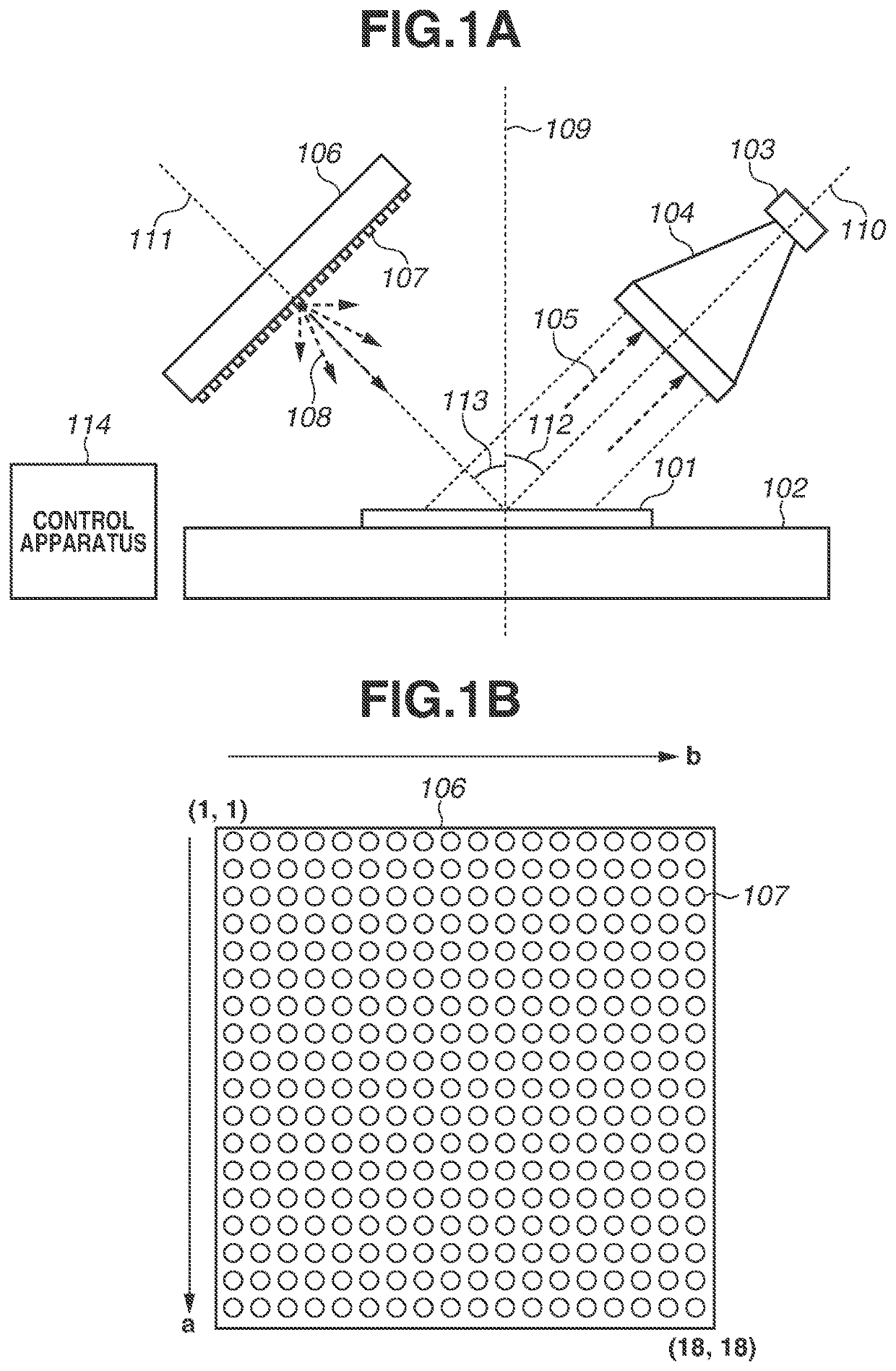
[0042]As described above, the control apparatus 114 according to the present exemplary embodiment controls the illumination device 106 including the plurality of light sources 107. The control apparatus 114 controls the illumination device 106 such that two or more of the plurality of light sources 107 are turned on when the object 101 is captured. The reflection characteristic of the object 101 is derived based on the image data obtained by capturing the object 101. When the illumination device 106 is controlled, the two or more light sources 107 are turned on such that the distance between the two or more light sources 107 is greater than a predetermined threshold value. This allows a reduction in the time required for the image capturing performed to acquire the reflection characteristic of the object 101. Furthermore, the information close to the information obtained when one of the light sources 107 is turned on may be acquired in each in...
second exemplary embodiment
Effect of the Second Exemplary Embodiment
[0055]As described above, the control apparatus 114 according to the present exemplary embodiment estimates the gloss image clarity of the target object based on the image obtained by pre-image capturing and calculates the illumination condition based on the estimated gloss image clarity. This makes it possible to simultaneously turn on the light sources 107 at an interval suitable for the target object and to derive the reflection characteristic of the target object with high accuracy.
[0056]According to the above-described exemplary embodiment, the lighting groups and the lighting order are determined based on the number of the simultaneously turned-on light sources 107; however, the lighting patterns specifying the lighting groups and the lighting order may be previously generated, and at least one of the lighting patterns may be selected based on a user's instruction, the gloss image clarity of the object, etc.
[0057]According to the presen...
PUM
 Abstract
Description
Claims
Application Information