Vehicle bed and cross rail attachment

a cross rail and vehicle bed technology, applied in vehicle arrangements, roofs, transportation and packaging, etc., can solve the problems of significant interference, additional manufacturing operations and manipulations, seams that are less aesthetically pleasing and visible when incorporated into the finished vehicle bed assembly,

Inactive Publication Date: 2006-12-26
NOBLE ADVANCED TECH
View PDF6 Cites 31 Cited by
  • Summary
  • Abstract
  • Description
  • Claims
  • Application Information

AI Technical Summary

Problems solved by technology

However, these downward flanges create significant interference problems at locations where they cross the underlying cross rails.
This severe notching of the flanges, however, creates an obvious and undesirable weakness in the floor at this area, and in addition requires additional manufacturing operations and manipulations.
This latter construction, however, results in the seam, namely the line created where the longitudinally adjacent edge flanges abut, being disposed in a raised rib, rather than in a valley between adjacent ribs, and it has been suggested that this causes the seam to be more visible and less aesthetically desirable when incorporated into the finished vehicle bed assembly.
While such notch does provide improved characteristics with respect to the construction of the floor panels and hence makes it unnecessary to notch or recess the edge flanges, nevertheless the presence of the notch in the cross rail provides a reduction in the strength and

Method used


Image

  • Vehicle bed and cross rail attachment
  • Vehicle bed and cross rail attachment
  • Vehicle bed and cross rail attachment

Examples


Embodiment Construction

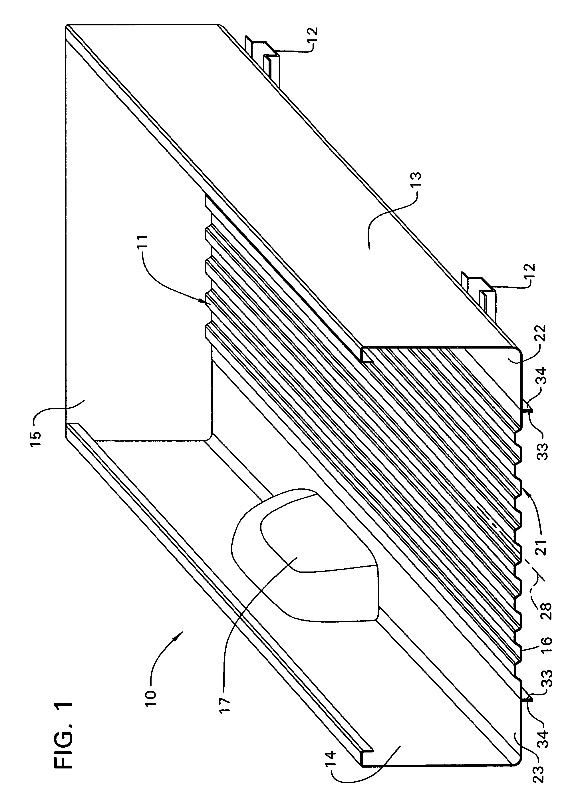
[0025]FIG. 1 is a fragmentary illustration of parts of a vehicle bed assembly 10, such as for a pickup truck. The bed assembly 10 includes a large and substantially horizontally extending floor or bed 11 intended for supporting loads thereon. This floor or bed 11 is, in a conventional manner, supported on a plurality of generally parallel and sidewardly spaced cross or frame rails 12 which extend transversely beneath the floor, only two such rails being diagrammatically illustrated in FIG. 1. The bed assembly includes right and left inner side walls 13 and 14, respectively, which are fixedly interconnected to and protrude substantially perpendicularly upwardly from the floor 11 adjacent opposite longitudinally extending side edges thereof. The inner side walls 13–14 in turn, at front edges thereof, are rigidly joined to a front wall or panel 15 which is fixed to and protrudes substantially perpendicularly upwardly from the front edge of the floor 11. The rear edge 16 of the floor 11...


PUM


Abstract

A bed arrangement for a vehicle including a horizontally large floor member defined by a thin metal sheet having a plurality of raised stiffening ribs extending lengthwise thereof. The floor member has a cantilevered edge flange extending along a lengthwise side edge thereof, which edge flange protrudes downwardly below a bottom surface of the floor member. A hat-shaped cross rail is disposed transversely under said floor member, and has a pair of top flanges which supportingly engages the bottom surface of the floor member. The cross rail, where it crosses the edge flange, has a depression formed therein to provide clearance for the edge flange. The top flanges having flange sections which are deformed downwardly to define the profile of the depression while maintaining the continuity of the top flanges as they extend lengthwise of the cross rail.

Description

FIELD OF THE INVENTION[0001]This invention relates to a bed construction for a vehicle, particularly a pickup truck, and more specifically to an improved floor and cross rail constructional arrangement.BACKGROUND OF THE INVENTION[0002]The bed assembly of pickup trucks typically include a horizontally large floor, the lengthwise extending side edges being joined to upright inner side walls, and the transverse front edge being joined to an upright front wall. The horizontally large floor is normally constructed from multiple pieces or panels, including a main or center floor panel extending the full length of the bed and having a width which is generally slightly less than the width between the wheel well openings. The floor also includes side floor panels which extend sidewardly between the center floor panel and the adjacent inner side walls. The side floor panels typically have wheel well openings formed therein, and wheel well housings close the openings and are secured to the sid...

Claims


Application Information

Patent Timeline
IPC IPC(8): B62D25/20
CPCB62D25/2054B62D27/02B62D33/02B62D65/02B62D25/20
Inventor MCNULTY, FRANK G.ENGLER, EDWARD J.
Owner NOBLE ADVANCED TECH
Why Eureka
Try Eureka