Displacement pump with variable volume flow

a variable-volume flow, displacement pump technology, applied in the direction of rotary or oscillating piston engines, engine lubrication, rotary piston engines, etc., can solve the problems of inability to arbitrarily reduce the diameter of the gear ring running set, the outer diameter of the variable pump is too large, and the design space of the variable pump is reduced. , to achieve the effect of reducing hydrostatic losses, reducing hydrostatic losses, and compactness of the variable-volume pump according to

Inactive Publication Date: 2005-09-29
HARLE HERMONN +1
View PDF10 Cites 7 Cited by
  • Summary
  • Abstract
  • Description
  • Claims
  • Application Information

AI Technical Summary

Benefits of technology

[0010] By omitting the variable ring around the external rotor and by increasing the speed of the internal rotor in proportion to the numbers of teeth from the external rotor to the internal rotor as compared to the drive speed, the design space of the variable pump required is reduced superproportionally, for the same specific delivery amount.
[0011] Such a variable pump in accordance with the invention is thus also suitable for small-volume internal combustion engines, in which particular value is placed on reducing the hydrostatic losses and the circulated amount of oil at high speeds.
[0012] The compactness of a variable displacement pump in accordance with the invention can h

Problems solved by technology

However, it has proven in practice that the design space available in increasingly compact reciprocating piston motors is becoming smaller and smaller.
Since these pumps are preferably arranged in the oil sump of the crankcases and since a mass-balance shaft often also has to be additionally accommodated in this region, together with other influencing factors such as conductor frame fortification of the crankcase and a highly pitched oil pan for ground clearance and the a

Method used


Image

  • Displacement pump with variable volume flow
  • Displacement pump with variable volume flow
  • Displacement pump with variable volume flow

Examples


Embodiment Construction

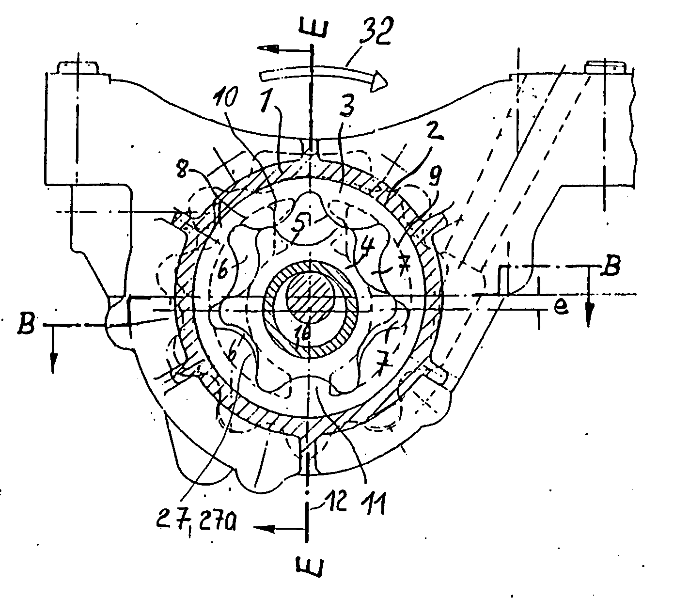
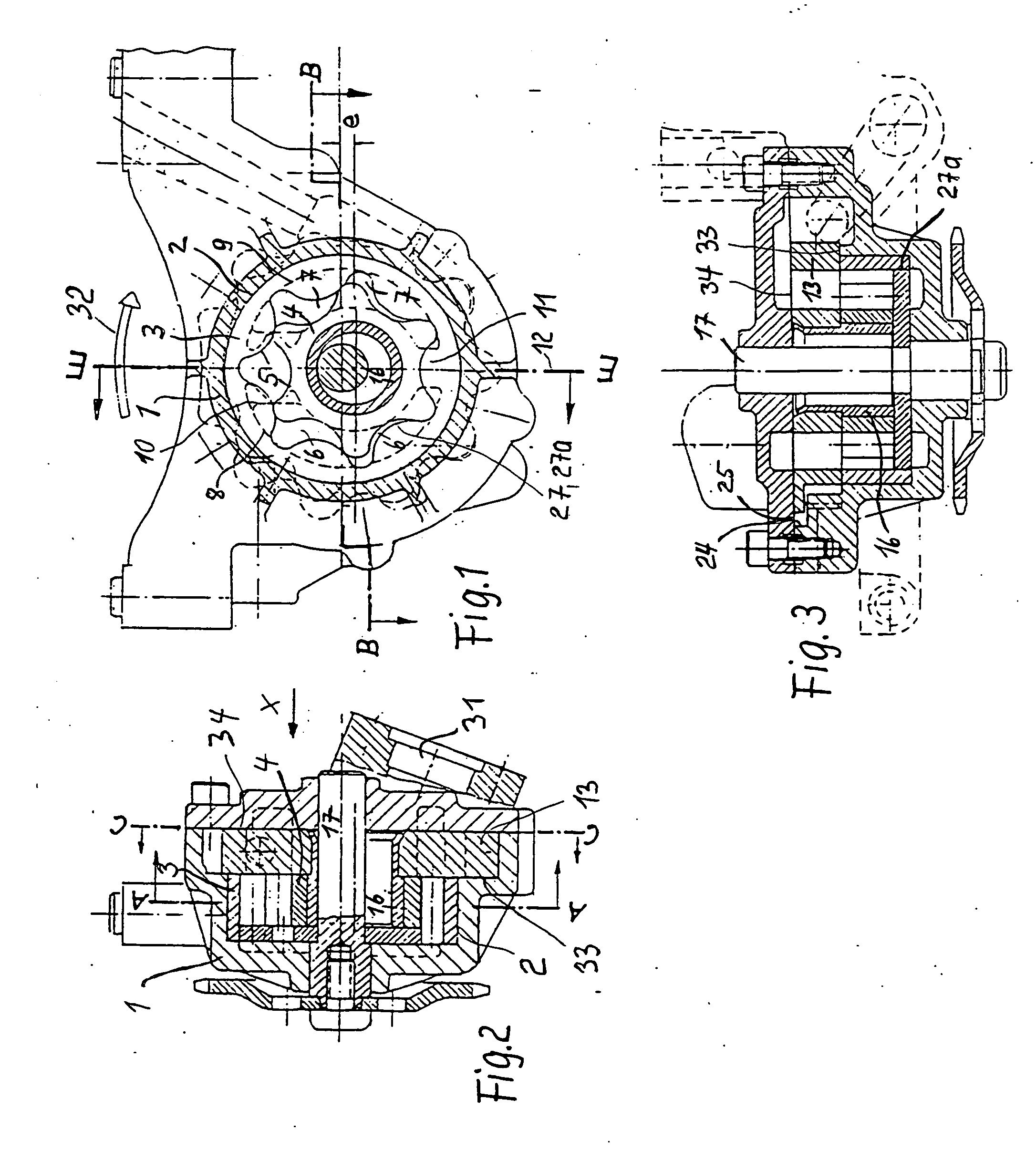
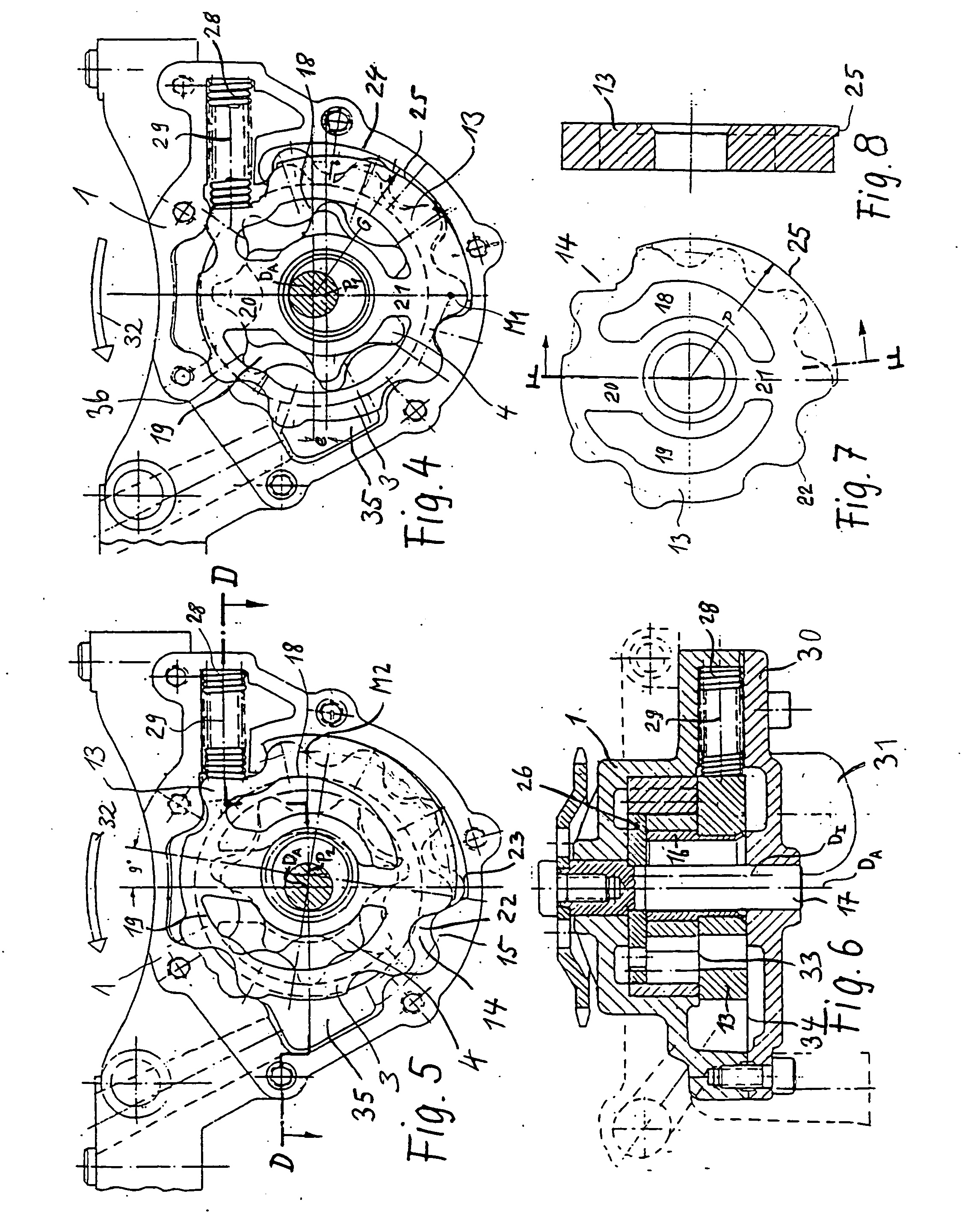
[0029] For explaining the function in the individual figures, the rotational direction of the running set shall be in the indicated direction of the arrow 32, such that the respective suction and pressure side in accordance with the expanding and compressing delivery cells of the teeth is clearly provided. In the cover 30, the suction support 31 is arranged on the suction side of the running set, on which side the variable spring 28 can also be seen. Thus, the spaces of the variable spring 28 and the rolling cylinders 24 and 25, and the sections of the toothing shown on the right of the image in FIGS. 4, 5, 6 and 7 between the variable plate 13 and the casing 1 are under suction pressure, since the variable plate 13 is fitted in between the cavern base 33 of the casing and the casing-cover partition line, forming an axial seal but able to move. The pressure space 35, which is hydraulically connected to the compressing delivery cells of the gear ring running set with the minimum poss...


PUM


Abstract

A displacement pump with variable volume flow having a casing; a chamber with an inlet opening on a low pressure side and an outlet opening on a high pressure side for a fluid; an internal rotor capable of rotation about a rotational axis (DI); a ring having a central ring axis (DA) surrounding the internal rotor and forming together with the ring, at least one delivery cell in which fluid is delivered from a low pressure side to a high pressure side of the pump; and an adjusting device which, during an adjusting movement, rolls off on the casing without slipping is provided. The internal rotor is fixed to the adjusting device and rotatble about the rotational axis (DI), and the position of the rotational axis (DI) relative to the central ring axis (DA) of the ring is adjusted by the adjusting movement of the adjusting device.

Description

FIELD OF THE INVENTION [0001] The invention relates to displacement pumps, in particular internal-axle gear pumps, but also wing cell pumps or for example also pendulum slider pumps, whose volume flow can be varied according to requirement, i.e. can be adjusted. The pumps in accordance with the invention are preferably used as lubricant oil pumps for internal combustion engines, wherein the internal combustion engine itself preferably drives the lubricant oil pump in question. The internal combustion engine can in particular be a drive motor, preferably a piston motor, of a vehicle. The specific volume flow, i.e. the volume flow delivered per revolution of a delivery wheel of the pump, can preferably be adjusted continuously. The displacement pumps can also be advantageously used as supply pumps for automatic transmissions in vehicles and when used in this way are also preferably driven by the drive motor of the vehicle in question. Although the displacement pump of the invention, w...

Claims


Application Information

Patent Timeline
IPC IPC(8): F01C1/02F01C1/063F01C1/24F01L1/34F04C2/10F04C14/14
CPCF04C14/14F04C2/10
Inventor HARLE, HERMONNEISENMANN, SIEGFRIED A.
Owner HARLE HERMONN
Why Eureka
Try Eureka