Device for curing obesity using cooling

Active Publication Date: 2016-06-23
CLASSYS CO LTD
View PDF5 Cites 31 Cited by
  • Summary
  • Abstract
  • Description
  • Claims
  • Application Information

AI Technical Summary

Benefits of technology

[0017]As described above, the present invention is advantageous in that metallic cooling plates are in-molded in a suction cup made of a silicone material, in which the metallic cooling plates make contact with a part to be treated via a thin silicone layer instead of making direct contact with the part to be treated so that the device efficiently destroys fat using a small amount of anti-freezing agent while protecting a skin, and removes any gap through which air flows in, thereby increasing suction force.
[0018]Furthermore, the present invention is advantageous in that the anti-freezing agent is applied to th

Problems solved by technology

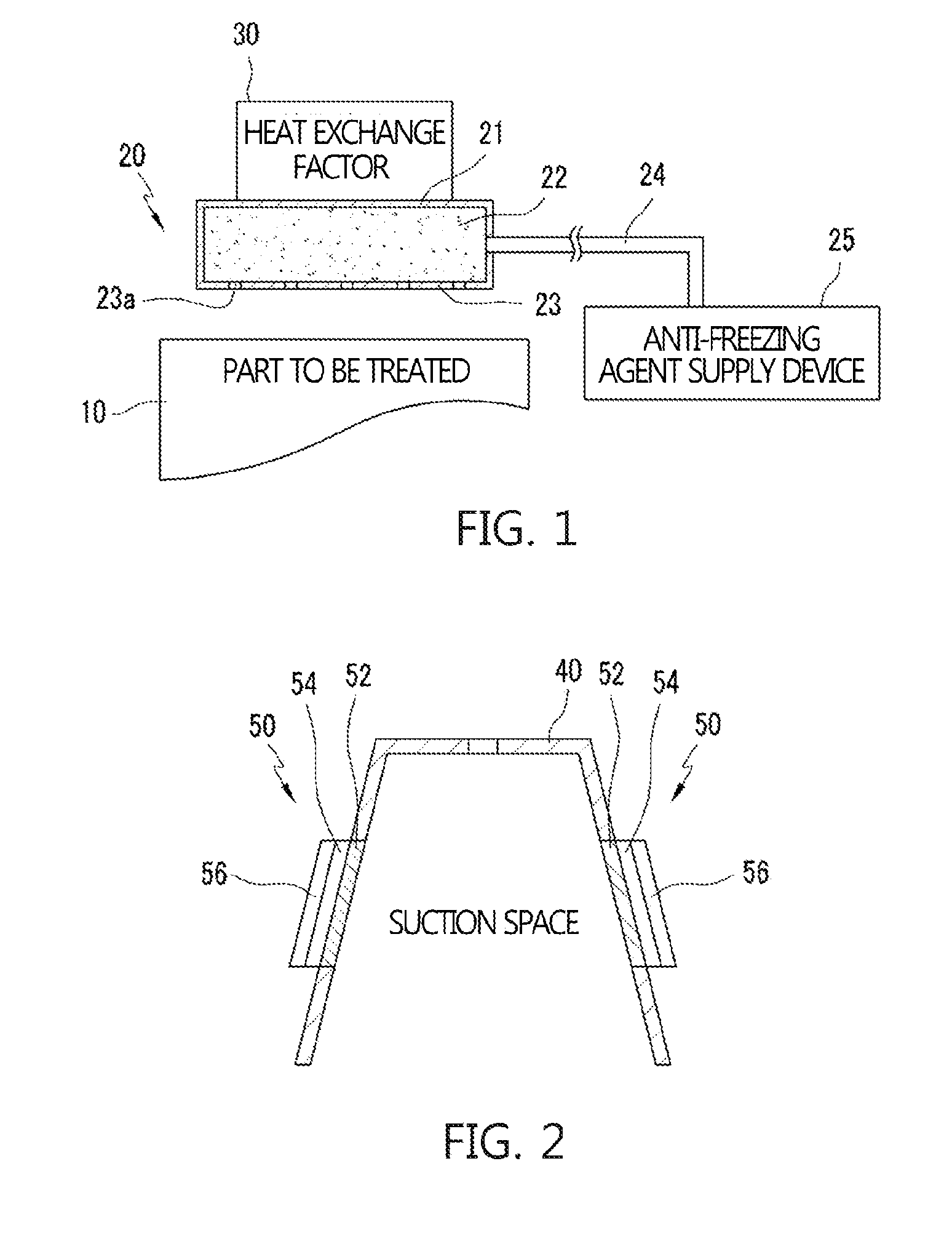
However, in the registered patent documents described above, as shown in FIG. 1, a coupling device or an absorption pad to provide an anti-freezing agent between a part to be treated and a heat exchange factor is required, and thus treatment expense is increased due to the increased number of

Method used


Image

  • Device for curing obesity using cooling
  • Device for curing obesity using cooling
  • Device for curing obesity using cooling

Examples


Example

[0043]FIG. 7 is a first embodiment of the spacer mounted or demounted on the suction cup of the handpiece according to the present invention. Further, FIG. 7(a) is a perspective view of a fixed sized spacer 160, and FIG. 7(b) is a cross-sectional view of a state of the fixed sized spacer 160 mounted on the suction cup.

[0044]As shown in FIG. 7, in the device for treating obesity using cooling according to the present invention, thickness of the bottom surface of the suction cup 140 is increased by inserting the fixed sized spacer 160 having a penetration hole 160a into the suction cup 140. Thus, the size of the suction space 148 is decreased, thereby reducing the part to be treated 10 sucked therein. That is, according to the related art, in case of a low rate of obesity or the small size of part to be treated, it is required to replace the suction cup with a small sized suction cup. However, according to the present invention, the size of the suction space 148 may be easily controll...

Example

[0045]FIG. 8 is a second embodiment of the spacer mounted or demounted on the suction cup of the handpiece according to the present invention. Further, FIG. 8(a) is a perspective view of a variable sized spacer 260, FIG. 8(b) is a view of an extended state of the variable sized spacer 260, and FIG. 8(c) is a view of a shortened state of the variable sized spacer 260.

[0046]The variable sized spacer 260 according to the present invention, as shown in FIG. 8, includes: a bottom plate 262; a top plate 261 to which support columns 261a and 261b, having coupling grooves formed at predetermined intervals, are attached; and a coupling member 264 for varying a distance between the bottom plate 262 and the top plate 261 by adjusting a coupled location at the coupling grooves. Thus, the suction space of the suction cup may be controlled. Further, the penetration hole 263 is formed in the top plate 261 and the bottom plate 262, and the coupling member 264 includes a button 264a protruding from ...


PUM


Abstract

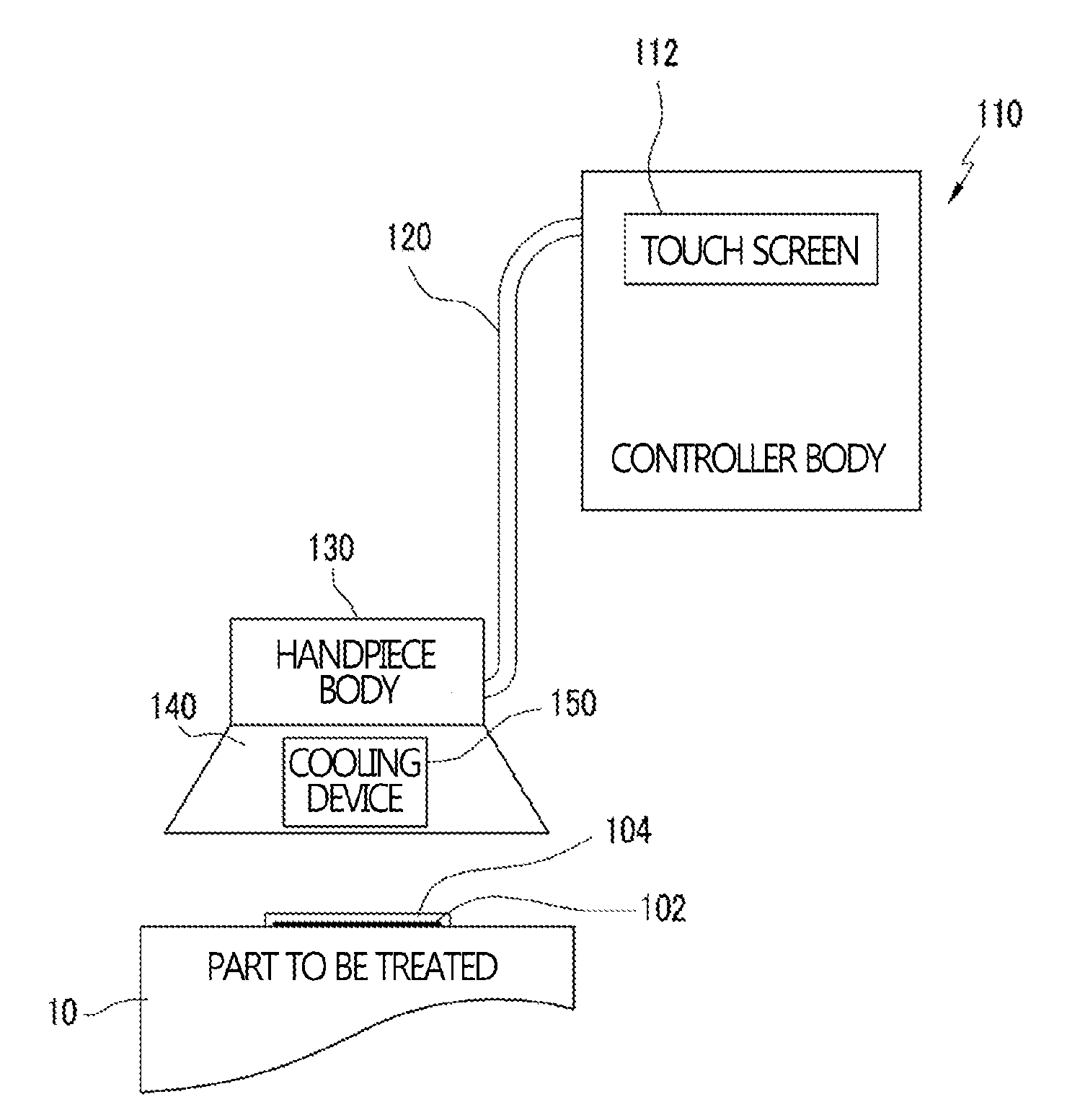
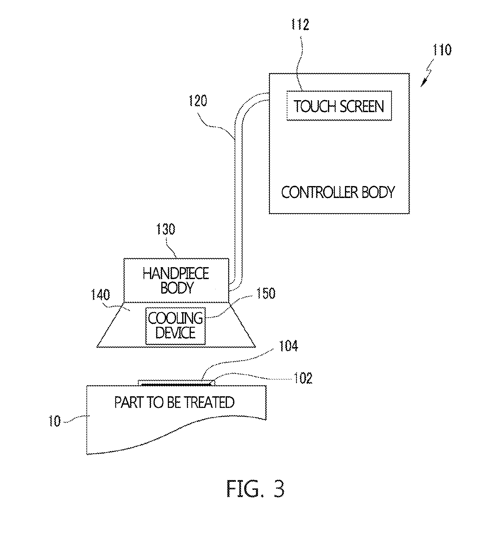
The present invention relates to a device for treating obesity using cooling, the device comprising: a controller body for setting a cooling temperature and operating time, supplying cooling water for cooling a thermoelectric element, and providing suction force through a vacuum pump; a handpiece body for displaying operating conditions and providing suction force through a suction hole; a cable for connecting the controller body and the handpiece body; a suction cup mounted on the handpiece body to form a suction space; and cooling devices positioned on opposite sides of the suction cup to cool a part to be treated, which has been sucked into the suction space. Further, metallic cooling plates in-molded in a suction cup made of silicone make contact with the part to be treated via a thin silicone layer such that fat can be destroyed efficiently using a small amount of anti-freezing agent while protecting the skin.

Description

TECHNICAL FIELD[0001]The present invention relates generally to a device for treating obesity using cooling. More particularly, the present invention relates to a device for treating obesity using low-cost cooling, the device being capable of treating obesity by spreading an anti-freezing agent to a part to be treated without use of an absorption pad or a coupling device, but by surrounding the part with a film to protect a skin, and cooling only a fat portion.BACKGROUND ART[0002]As well known to those skilled in the art, obesity is caused mainly by the accumulation of neutral fat in such a way that fatty acid and glucose introduced from blood plasma to fat cells are esterified when excessive nutrients are consumed compared to the amount of energy consumption over a long period. Further, when a body mass index (a value obtained by dividing weight in kilograms by height in meters squared) is the reference value (25) or more, it is viewed as being at the level of obesity.[0003]Since i...

Claims


Application Information

Patent Timeline
IPC IPC(8): A61H39/06A61B18/02
CPCA61H39/06A61B18/02A61B2018/00291A61B2018/00464A61B2018/00702A61B2018/00791A61H2205/083A61B2090/0463A61H2201/0214A61H2201/0242A61H2201/0285A61H2201/5082A61B2018/025A61F7/007A61F2007/0075A61F2007/0096A61F2007/029A61H2201/165
Inventor JUNG, SUNG JAE
Owner CLASSYS CO LTD
Why Eureka
Try Eureka