Method for relieving suction force in a pool drain

Active Publication Date: 2011-05-03
PARAMOUNT POOL & SYST
View PDF16 Cites 6 Cited by
  • Summary
  • Abstract
  • Description
  • Claims
  • Application Information

AI Technical Summary

Benefits of technology

[0006]Implementations of a hydraulic suction fuse may utilize a first method of relieving the suction force in a swimming pool or spa. The method may include the steps of closing an aperture in a hydraulic s

Problems solved by technology

The drain at the bottom of a swimming pool can pose a safety hazard to an occupant of the pool, particularly a young child or a person of limited physical strength.
If such strength is not available or if the user panics, drowning may result.
Furthermore, even if the user is capable of pushing away from the drain, injury of more or less seriousness may result.
Some of these devices introduce air to the inlet side of the pump in response to the sensed high suction condition, which results in loss of pump prime.
There are numerous problems attendant existing prior art devices, which problems will be summarized below.
Many of the devices are very expensive and have many moving parts.
Installation of some devices may require several feet of excavation for installation purposes which render them expensive and the resulting deterrent may preclude installation.
Depending upon the system installed, the pump may be damaged upon actuation with the resulting attendant problems of expense and loss of use of the swimming pool.

Method used


Image

  • Method for relieving suction force in a pool drain
  • Method for relieving suction force in a pool drain
  • Method for relieving suction force in a pool drain

Examples


Embodiment Construction

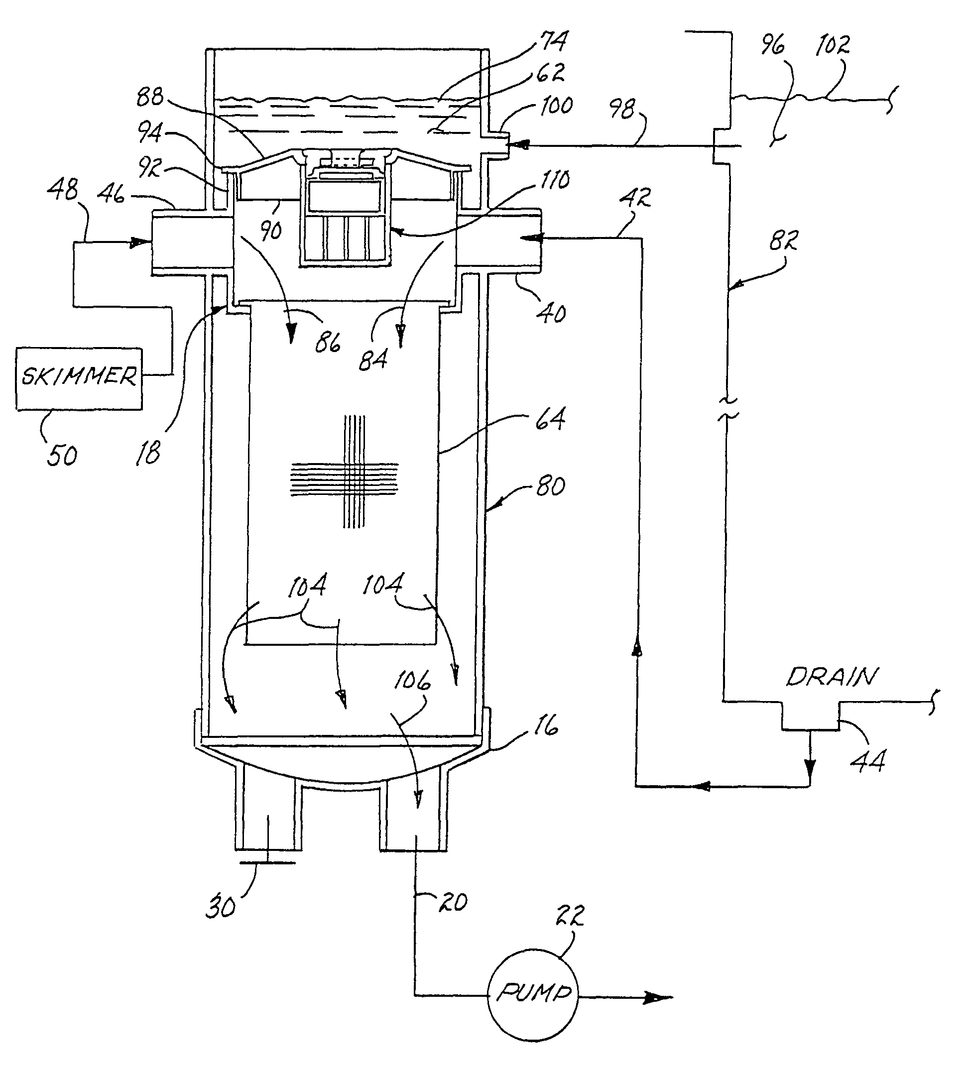
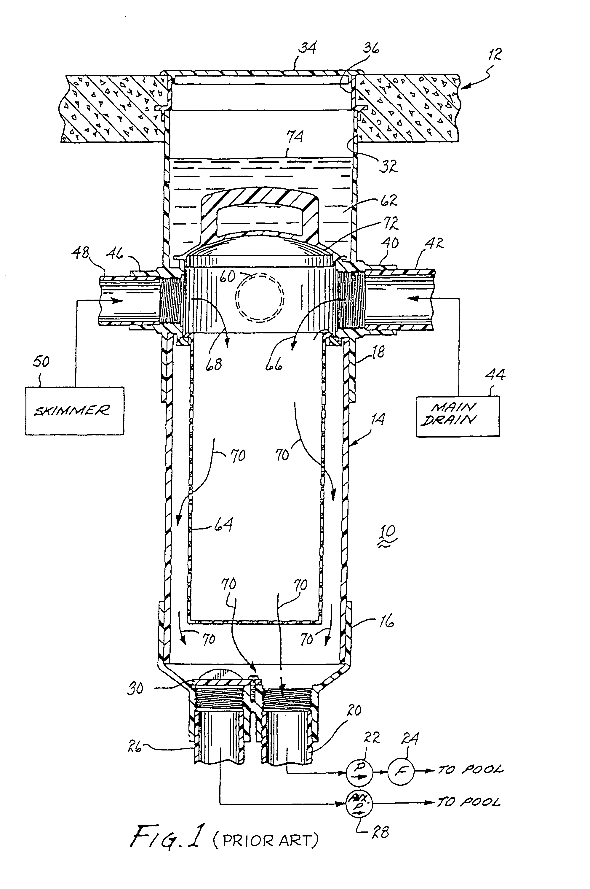
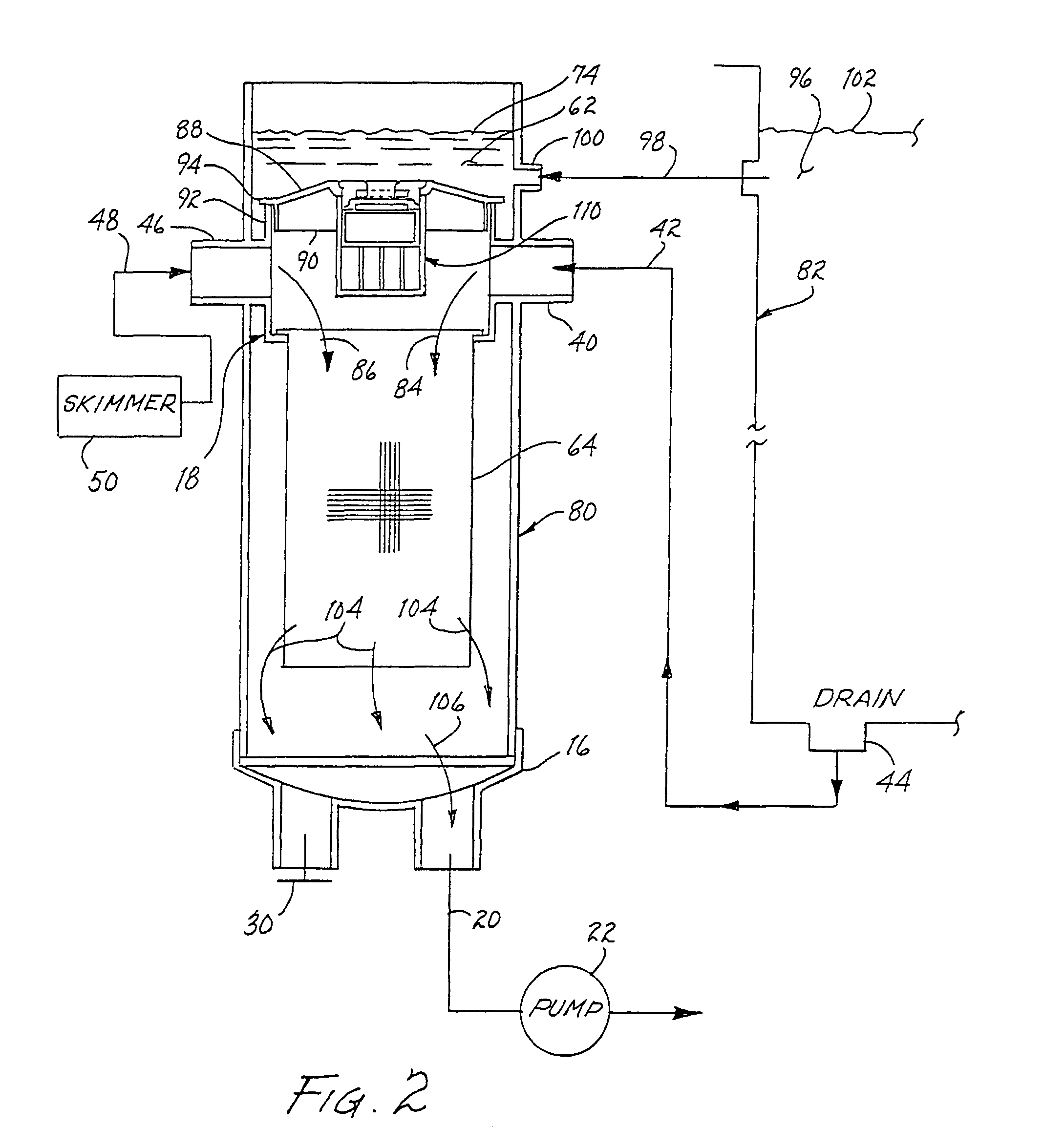
[0030]Referring to FIG. 1, there is illustrated a debris collection trap 10 of the type described in U.S. Pat. No. 5,265,631 (hereinafter referred to as the '631 patent). The trap is located adjacent the side of a swimming pool and recessed below the surface of pool deck 12. Such location permits the trap to be made relatively large for significant capacity without being obtrusive to users of the swimming pool. The trap includes an elongated tank 14 having a bottom closure unit 16 and top inlet unit 18. The closure unit may include a first outflow pipe 20 conveying water to a pump 22 and a filter 24 downstream thereof to filter the water received. The water is then returned to the pool, as indicated. Closure unit 16 may include a second pipe 26 conveying water to an auxiliary pump 28 that provides water to a cooling spray, waterfall, or other water emitting elements attendant the pool, as indicated. A closure 30, such as a pivotal plate illustrated, may be incorporated to selectivel...


PUM


Abstract

Methods of relieving the suction force in a swimming pool or spa. A first method may include the steps of closing an aperture in a hydraulic suction fuse through magnetic force and opening the aperture by increasing suction force within the hydraulic suction fuse. Implementations of hydraulic suction fuses may also utilize a method of adjusting the fuse point of a hydraulic suction fuse. The method may include decoupling a magnet assembly from a first step having a first height, the first step contained in a fuse body contained in the hydraulic suction fuse. The method may also include rotating the magnet assembly and coupling the magnet assembly with a second step having a second height, the second step contained in the fuse body.

Description

CROSS REFERENCE TO RELATED APPLICATIONS[0001]This application is a continuation-in-part of application Ser. No. 11 / 457,361, filed Jul. 13, 2006, entitled “METHOD FOR RELIEVING SUCTION FORCE IN A POOL DRAIN” to Goettl, which application is a division of and claims priority to an application entitled “A MANUALLY RESETTABLE HYDRAULIC SUCTION FUSE FOR SWIMMING POOLS”, assigned Ser. No. 11 / 319,638, filed Dec. 28, 2005, now U.S. Pat. No. 7,089,606, issued Aug. 15, 2006, which application is a division of and claims priority to an application entitled “HYDRAULIC SUCTION FUSE FOR SWIMMING POOLS”, assigned Ser. No. 11 / 008,767, filed Dec. 8, 2004, now U.S. Pat. No. 7,055,189, issued Jun. 6, 2006, which application is a division of and claims priority to an application entitled “HYDRAULIC SUCTION FUSE FOR SWIMMING POOL”, filed Apr. 16, 2003, assigned Ser. No. 10 / 417,872, now U.S. Pat. No. 6,895,608, issued May 24, 2005, the disclosures of which are hereby incorporated herein by reference.BACKG...

Claims


Application Information

Patent Timeline
IPC IPC(8): E04H4/00
CPCE04H4/1236
Inventor GOETTL, JOHN M.CONN, R. DOMINICBARNES, STEVEN R.
Owner PARAMOUNT POOL & SYST
Why Eureka
Try Eureka