
A butt joint device of a single rivet clamp automatic assembly machine

A docking device and assembly machine technology, applied in the field of clamp processing, can solve the problems of cumbersome operation, high labor intensity, low efficiency, etc., and achieve the effect of increasing the suction force

Active Publication Date: 2019-12-03
平邑仁安中医药产业发展有限公司
View PDF6 Cites 0 Cited by
  • Summary
  • Abstract
  • Description
  • Claims
  • Application Information

AI Technical Summary

Problems solved by technology

Therefore, in actual production, after the independent sub-parts are cast, it is necessary to align and splice the two opposite sub-parts so that the riveting holes at the two overlapping ends are connected, and the rivets will be put in later, and finally stamped to obtain the finished product. Most of the clamp butt joint methods still use manual processing. It takes at least 2 to 3 minutes for a skilled manual to assemble a clamp. It can be seen that this butt joint assembly method is cumbersome to operate, labor-intensive, and low in efficiency. Nowadays, the market For the huge demand for clamps, the previous method of manually assembling clamps has been unable to meet the needs of the market.

Method used


Image

  • A butt joint device of a single rivet clamp automatic assembly machine
  • A butt joint device of a single rivet clamp automatic assembly machine
  • A butt joint device of a single rivet clamp automatic assembly machine

Examples


Embodiment Construction

[0028] Below in conjunction with accompanying drawing and embodiment of description, specific embodiment of the present invention is described in further detail:

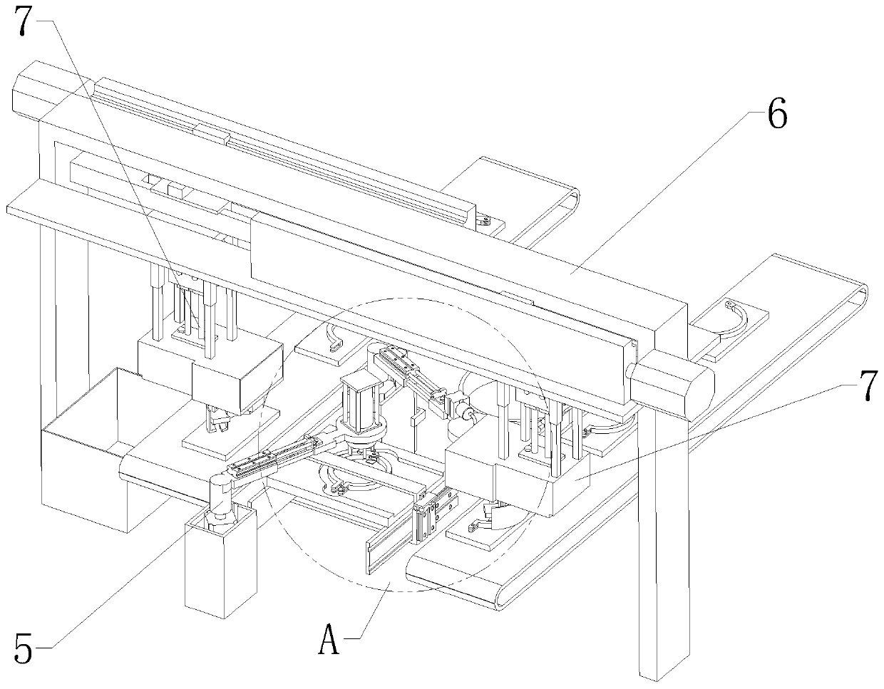
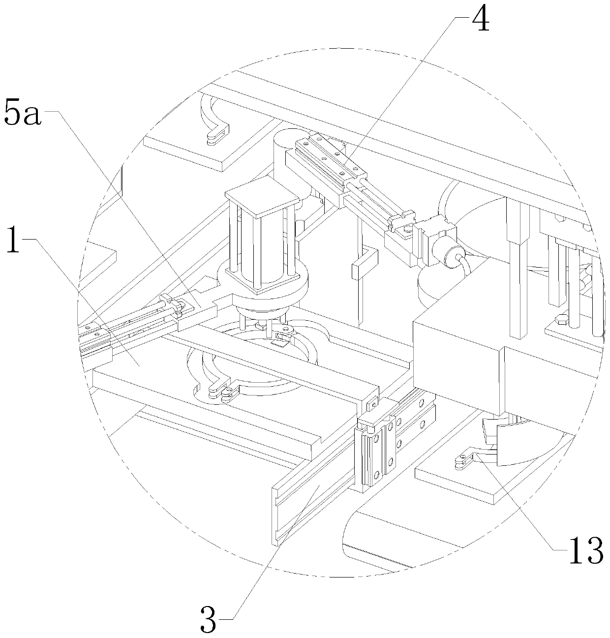
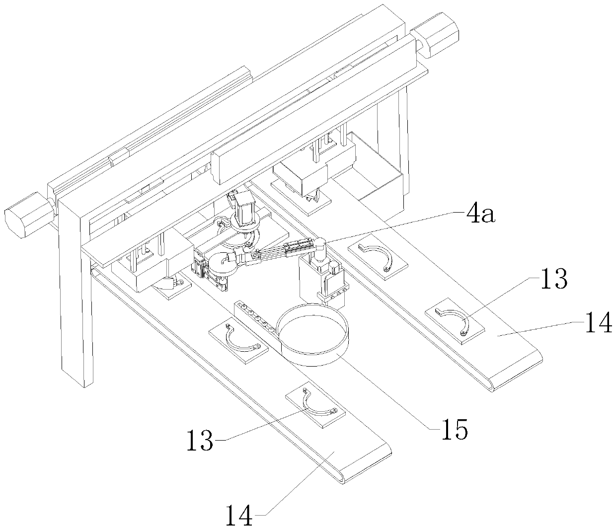
[0029] refer to Figure 1 to Figure 12The described automatic assembly machine for single rivet clamps includes two symmetrical conveyor belts 14, and also includes a butt joint device for splicing the two sub-parts 13 of the clamp 12, which is arranged between the two conveyor belts 14 And also located at the downstream end of the two support limit devices and the rivet feeding device 4 and the lower pressure riveting device 5 symmetrically arranged on both sides of the support limit device, the support limit device includes the processing plate 1 and is arranged on the processing plate 1 above and capable of horizontal movement of the limit assembly 3, the rivet feeding device 4 includes a first transfer mechanical arm 4a and a rivet absorber, the rivet absorber is rotatably arranged above the processing plate 1 t...


PUM


Abstract

The invention relates to the field of clamping hoop machining, in particular to a butt-joint device for a single-rivet clamping hoop automatic assembling machine. The butt-joint device comprises a portal frame and two symmetrical conveying belts and further comprises two butt-joint assemblies, a power assembly and a machining plate, wherein the two butt-joint assemblies are used for splicing two subparts of a clamping hoop; the power assembly is used for driving the two butt-joint assemblies to be capable of moving horizontally independently; and the machining plate is used for allowing the two subparts in the clamping hoop to be placed thereon. The portal frame stretches across the two conveying belts and arranged at the downstream ends of the two conveying belts. The power assembly is arranged at the top of the portal frame. The two butt-joint assemblies are symmetrically arranged at the two ends of an opening of the portal frame and are the same in structure. The machining plate isarranged between the two conveying belts and located below the portal frame. By means of the butt-joint device, the alignment and splicing work of the two subparts of the clamping hoop can be completed fully-automatically, and assembling efficiency of the clamping hoop is greatly improved.

Description

technical field [0001] The invention relates to the field of hoop processing, in particular to a butt joint device of a single rivet hoop automatic assembly machine. Background technique [0002] The clamp is a connection device for connecting grooved pipe fittings, valves and pipeline fittings, and is used to tighten the fast joints. The clamp is generally composed of two arc-shaped rings (sub-parts), one end of the two is overlapped and riveted, and the specifications between the two are similar. Therefore, in actual production, after the independent sub-parts are cast, it is necessary to align and splice the two opposite sub-parts so that the riveting holes at the two overlapping ends are connected, and the rivets will be put in later, and finally stamped to obtain the finished product. Most of the clamp butt joint methods still use manual processing. It takes at least 2 to 3 minutes for a skilled manual to assemble a clamp. It can be seen that this butt joint assembly m...

Claims


Application Information

Patent Timeline
Patent Type & Authority Patents(China)
IPC IPC(8): B21J15/32B21J15/42
CPCB21J15/323B21J15/42
Inventor 栾友祥
Owner 平邑仁安中医药产业发展有限公司
Learn More