Vacuum adsorbing device

Active Publication Date: 2013-04-04
WOO CHUL SEOK
View PDF8 Cites 2 Cited by
  • Summary
  • Abstract
  • Description
  • Claims
  • Application Information

AI Technical Summary

Benefits of technology

[0022]According to the embodiments of the present invention, a plurality of fixing pieces is formed inside a cover of the vacuum suction device, a plurality of elastic stoppers having a certain curved surface is formed in a height adjustment member in order for each of the fixing pieces to slide and move to be hung to be fixed, each of the fixing pieces slides and moves along a curved surface of the elastic stopper with each of the fixing pieces contacting to the curved surface to be hung on an one side surface of each of the elastic stoppers when the cover rotates, an outer surface of a suction plate of the vacuum suction device tightly contacts a adhered surface, a center part of the suction plate is lifted, and a vacuum-applied state is formed between the adhered surface and the suction plate, and thus, the suction force of the vacuum suction device is enhanced and the suction plate of the vacuum suction device is securely adhered to the adhered surface.
[0023]Moreover, according to the embodiments of the present invention, a spring used in a related art vacuum suction device is removed, a plurality of elastic stoppers are molded when a height adjustment member is being molded, and thus, the number of components configuring the vacuum suction device may decrease, and an assembly of each of elements configuring the vacuum suction device may be easily performed, whereupon an assembling work between each of the elements configuring the vacuum suction device, a work efficiency and productivity may be enhanced, thereby a manufacturing cost of manufacturing the vacuum suction device b

Problems solved by technology

Here, it is difficult that the vacuum suction device, which directly pushes the suction plate to the adhered surface to adhere the suction plate to the adhered surface, seals a space between the suction plate and the adhered surface, and suction force of the vacuum suction device between the suction plate and the adhered surface is weak.
Therefore, the suction plate is easily separated from the adhered surface, and thus, it is difficult for the vacuum device to be fixed to the adhered surface for a long time, and the vacuum suction device separated from the adhered surface has to be repeatedly adhered to the adhered surface, and thus, it is inconvenient to use the vacuum suction device.
Because It is very inconvenient to assemble or combine the spring, which makes the suction plate be adhered to the adhered surface by forming the vacuum-applied state between the adhered surface and the suction plate by using the elastic restoring force of the spring, or makes the suction plate be separated

Method used


Image

  • Vacuum adsorbing device
  • Vacuum adsorbing device
  • Vacuum adsorbing device

Examples


Embodiment Construction

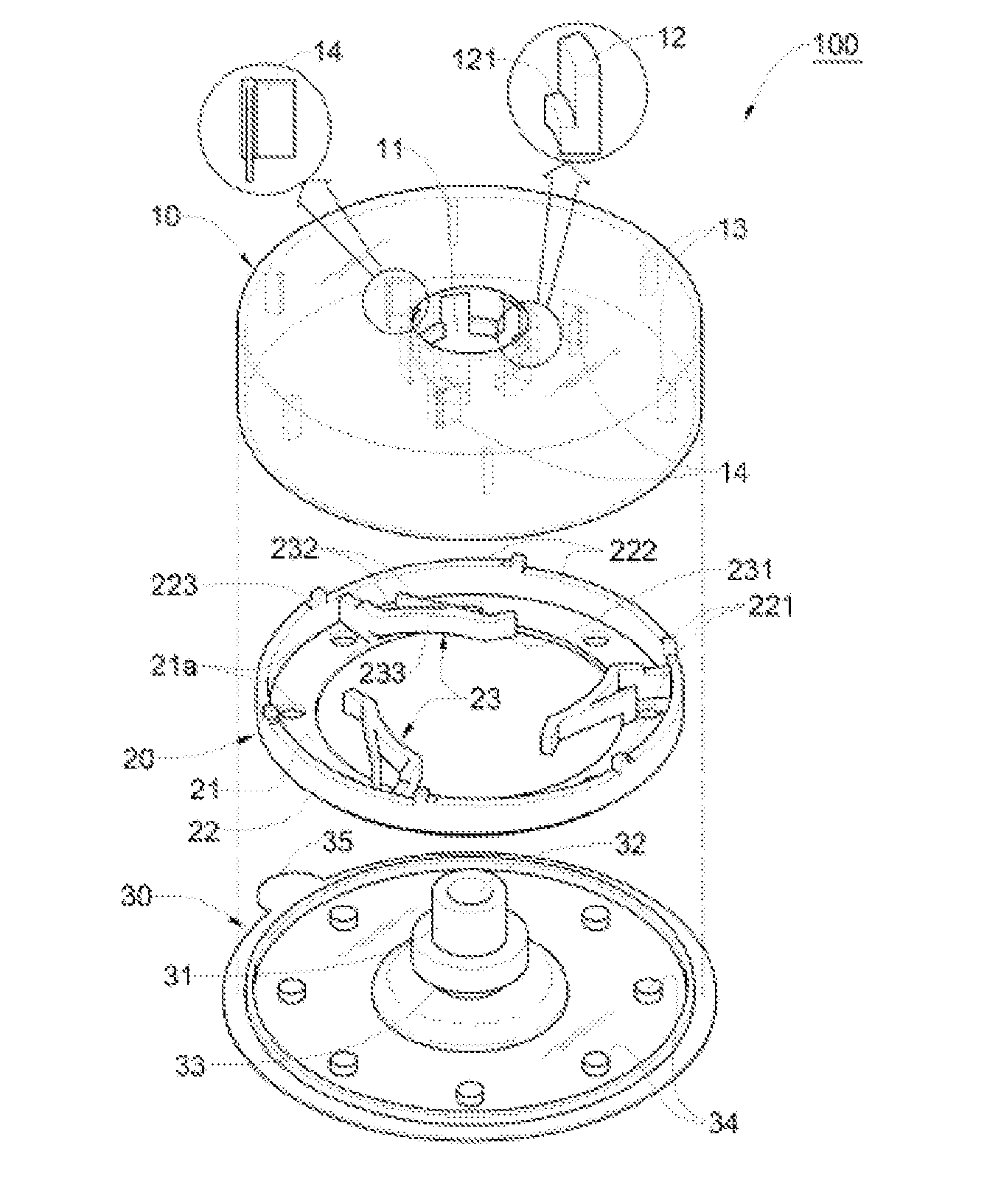
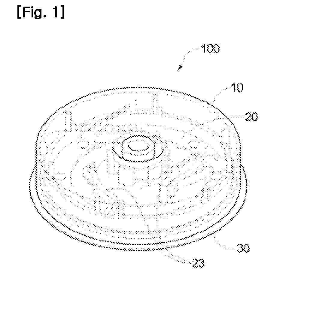
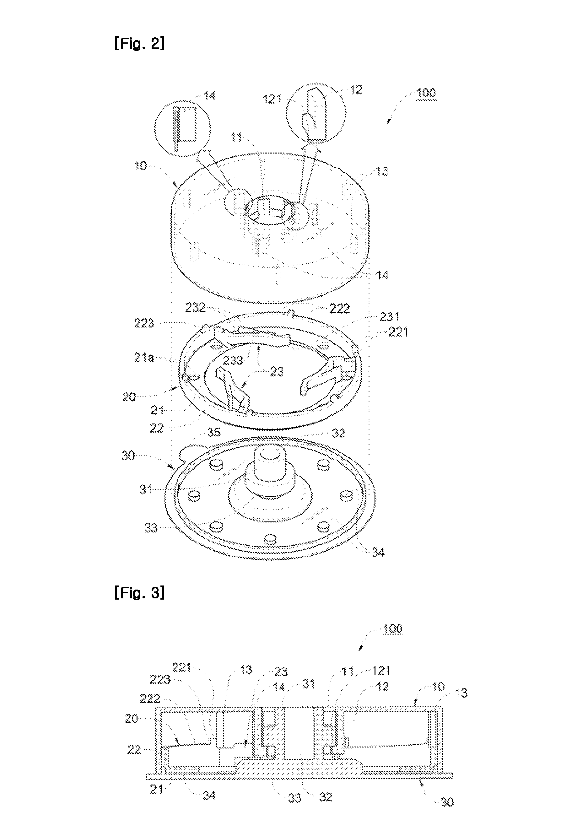
[0036]Reference will now be made in detail to the exemplary embodiments of the present invention, examples of which are illustrated in the accompanying drawings. Wherever possible, the same reference numbers will be used throughout the drawings to refer to the same or like parts. Hereinafter, the vacuum suction device according to the embodiments of the present invention will be described in detail with reference to FIGS. 1 to 9.

[0037]The vacuum suction device 100 according to the present invention is adhered to an adhered surface (a), that is, a smooth surface or a flat surface such as a glass, a tile or the like by means of vacuum suction in order for a towel, toilet paper or the like to be hung on the adhered surface.

[0038]The vacuum suction device 100, as shown in FIGS. 1 to 3, includes a cover 10 which is rotatably mounted on the upper portion, an suction plate 30 which is coupled to the inside of the lower portion of the cover 10 to be adhered to the adhered surface (a) by vac...


PUM


Abstract

A vacuum suction device of the present invention comprises: a cover which is rotatably mounted on the upper portion so as to couple to a flat surface by means of vacuum suction; an suction plate, which is coupled to the lower portion of the cover, for vacuum suction to the flat surface; and a height adjustment member, which is arranged between the cover and the suction plate, for moving the suction plate back and forth according to the rotation of the cover; wherein a plurality of fixing pieces are formed on the upper surface of the inside of the cover, a plurality of elastic stoppers are coupled to the inside of the height adjustment member, so as to be movable by sliding when each of the fixing pieces is in contact, and for fixing the cover by each of the fixing pieces being hooked to the end portion of the cover so as to prevent reverse rotation. The vacuum suction device of the present invention enhances suction force so as to couple the vacuum suction device to the flat surface more solidly and for a longer time, enhances assembly between each of the elements for vacuum suction, and prevents unlocking due to outside shock by forming a double locking structure in the vacuum adsorption device.

Description

TECHNICAL FIELD[0001]The present invention relates to a vacuum suction device including a hanging member in order for a towel, toilet paper or the like to be hung on the hanging member, and more particularly, to a vacuum suction device, which enhances suction force so as to be coupled to a flat surface by means of vacuum suction more solidly and for a longer time, and enhances an assembling work between each of the elements configuring the vacuum suction device.BACKGROUND ART[0002]Generally, a vacuum suction device is a member which is adhered to a surface by means of vacuum suction in order for objects of various shapes such as a towel, toilet paper or the like to be hung on a flat surface such as a glass, a tile or the like.[0003]The vacuum suction device includes a hanging member and a suction plate, the hanging member is formed for a towel, toilet paper or the like to be hung on the hanging member, and the suction plate is adhered to a smooth surface or a flat surface such as a ...

Claims


Application Information

Patent Timeline
IPC IPC(8): F16M13/02
CPCF16B47/00F16M13/022F16M13/02
Inventor WOO, CHUL SEOK
Owner WOO CHUL SEOK
Why Eureka
Try Eureka