Parabolic reflector and antenna incorporating same

a technology of reflector and antenna, applied in the direction of antennas, radiating element housings, electrical devices, etc., can solve the problems of low losses, increase in conductor losses in the associated feed network, and gain limit of about 30 db, so as to achieve the effect of reducing the depth of the reflector

Inactive Publication Date: 2007-10-09
TELEFON AB LM ERICSSON (PUBL)
View PDF7 Cites 7 Cited by
  • Summary
  • Abstract
  • Description
  • Claims
  • Application Information

AI Technical Summary

Benefits of technology

[0006]In accordance with a first aspect of the invention there is provided a parabolic reflector for an antenna comprising: a plurality of concentric annular sections arranged in series from a first annular section nearest a central axis of the reflector to a last annular section defining an outer perimeter of the reflector, each section having a parabolic reflecting surface between inner and outer perimeters, characterised in that the sections are configured such that the focal point or focal ring associated with at least the last section lies inside an internal volume of the reflector and are arranged with respect to each other along the central axis, such that an overall depth of the reflector is minimised or near-minimised. By ensuring that the focus of the reflector lies inside its internal volume this ensures that the overall depth of an antenna incorporating such an reflector is minimised since an antenna subreflector, which is positioned at the focus, will lie within the volume of the reflector.
[0007]Advantageously the inner perimeters of all the sections are arranged to lie substantially on a plane which is perpendicular to the central axis. Such an arrangement assists in minimising the depth of the reflector.

Problems solved by technology

These have an upper gain limit of about 30 dB, due to the fact that the conductor losses in the associated feed networks increase considerably with antenna size.
An alternative solution for higher gain are waveguide slot arrays, which have low losses but higher production costs.
All these antennas are more complicated than the simple printed array and require additional volume and thickness which is further increased by the presence of the radome, a flat dielectric plate placed a distance of approximately one wavelength above the antenna parallel to the array surface.
Two further aspects of this known design result in a considerable thickness of the entire antenna in the plane of the page.
Furthermore, the great length of the waveguide may increase the overall return-losses in a broadband system.

Method used


Image

  • Parabolic reflector and antenna incorporating same
  • Parabolic reflector and antenna incorporating same
  • Parabolic reflector and antenna incorporating same

Examples


Embodiment Construction

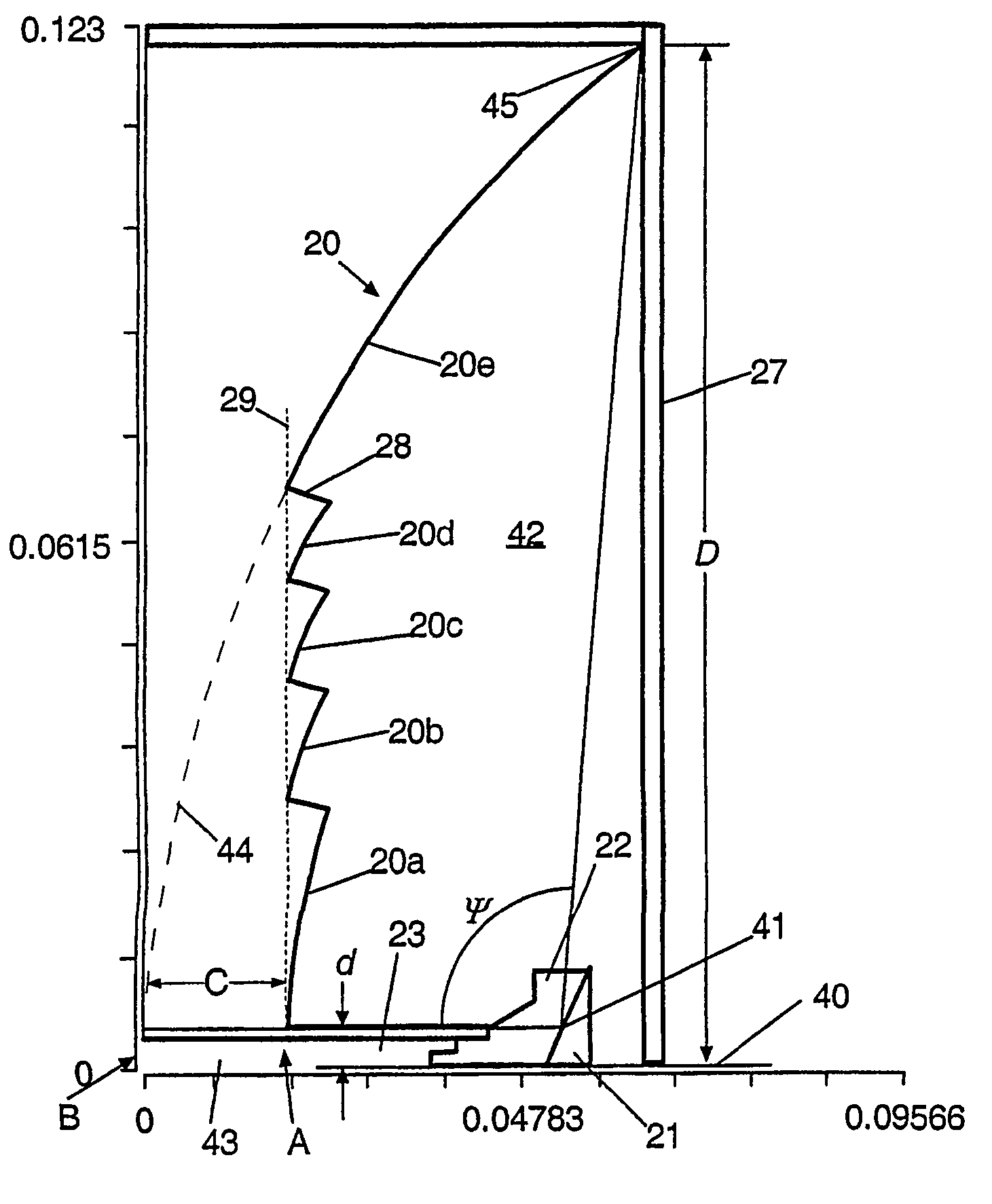
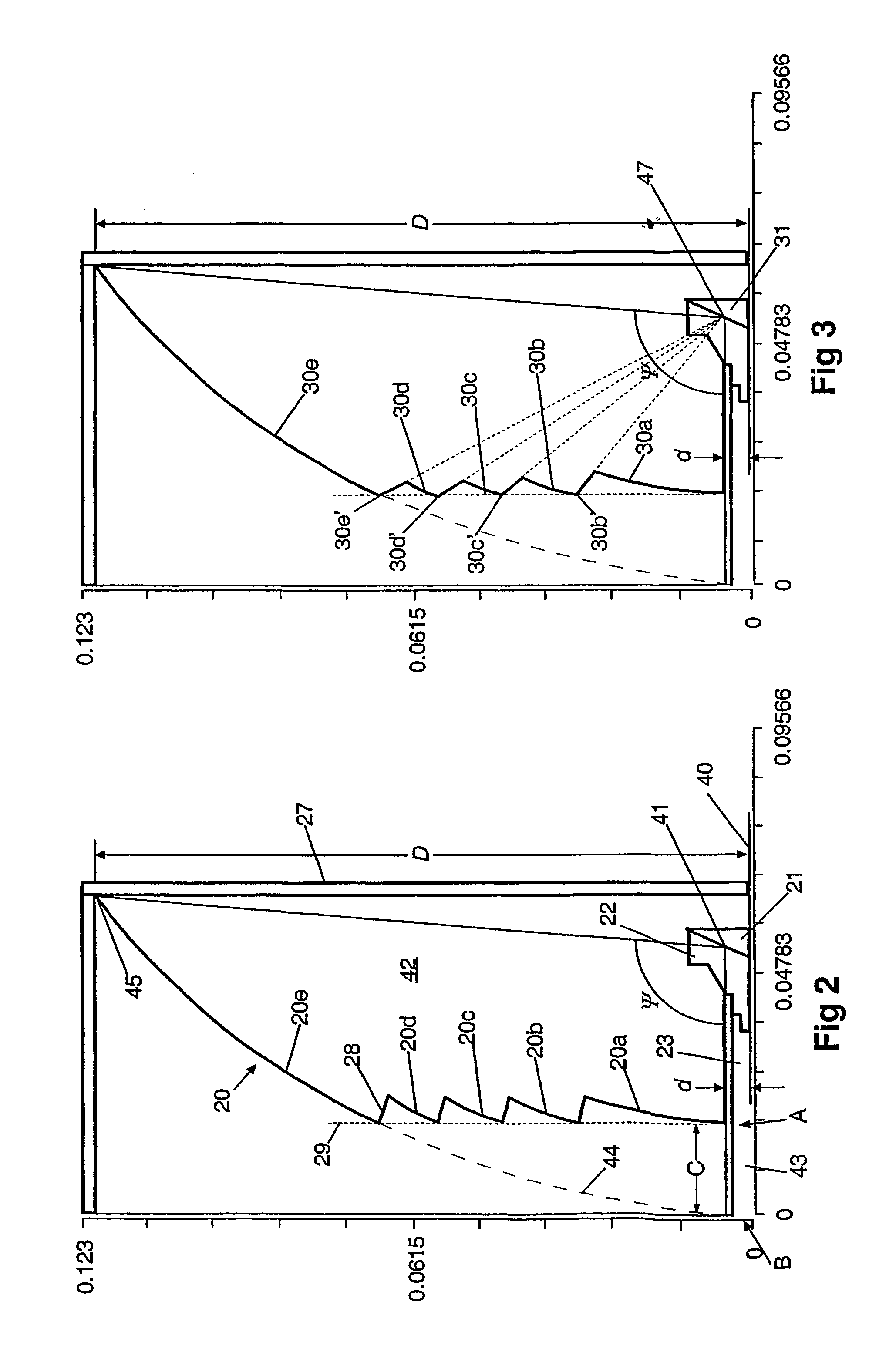
[0018]Referring now to FIG. 2, an embodiment of an antenna according to the present invention is shown, comprising as before a main reflector 20, a subreflector 21, a dielectric cone 22, a waveguide section 23 and a radome 27. This time, however, the reflector 20 is a multi-stage antenna, consisting of a plurality N of concentric annular sections 20a-20e (N=5 in this example) which are connected to each other via concentric annular strips 28. Each of the sections 20a-20e has a reflecting surface that is parabolic in a radial direction. The strips 28 connect the outer perimeters of the various sections (except the last section 20e) to the inner perimeters of the succeeding sections, there being formed thereby a continuous inner reflecting surface of the main reflector 20. The inner perimeter of the first section 20a forms part of the apex of the reflector 20, while the outer perimeter of the last section 20e forms the outer perimeter of the entire reflector 20.

[0019]In the illustrate...


PUM


Abstract

A parabolic reflector for an antenna has a plurality of concentric annular sections arranged in series from a first annular section nearest a central axis of the reflector to a last annular section defining an outer perimeter of the reflector. Each section has a parabolic reflecting surface between inner and outer perimeters. The sections are configured such that the focal point associated with at least the last section lies inside an internal volume of the reflector and are arranged with respect to each other along the central axis, such that an overall depth of the reflector is substantially minimized. The inner perimeters of all the sections are preferably arranged to lie substantially on a plane which is perpendicular to the central axis. The outer perimeter of each section except the last section is preferably connected with the inner perimeter of the succeeding section by means of an annular strip. The strips may either each have an angle of inclination to the reflector central axis of between 0° and 3° or they may lie on respective cones running from the respective inner perimeters of the respective sections to which they are joined, to the furthest located focal point or ring.

Description

BACKGROUND OF THE INVENTION[0001]In many communications systems space is at a premium and therefore efforts are made to make antennas as compact as possible, while retaining adequate performance characteristics. In point-to-multipoint (PMP) microwave radio links especially, flat antennas are often installed in the terminal units due to their compact design. They can be easily integrated into boxes containing the electrical equipment of the outdoor units without detracting from the quality of the urban environment. For medium-gain requirements printed antennas are preferred. These have an upper gain limit of about 30 dB, due to the fact that the conductor losses in the associated feed networks increase considerably with antenna size. An alternative solution for higher gain are waveguide slot arrays, which have low losses but higher production costs. Hybrid configurations are also feasible using a mixed design with microstrip subarrays and a central waveguide feed network. In the case...

Claims


Application Information

Patent Timeline
Patent Type & Authority Patents(United States)
IPC IPC(8): H01Q13/00H01Q15/14H01Q1/42H01Q15/16H01Q19/06H01Q19/12H01Q19/13H01Q19/19
CPCH01Q19/065H01Q19/134H01Q19/12
Inventor MAHR, ULRICH
Owner TELEFON AB LM ERICSSON (PUBL)
Why Eureka
Try Eureka