Self-sealing PTFE vascular graft and manufacturing methods

a vascular graft and self-sealing technology, applied in the field of vascular grafts, can solve the problems of reducing the overall radial tensile strength of the tube, reducing the ability of the graft to retain a suture, and low axial tear strength

Inactive Publication Date: 2004-09-30
LIFEPORT SCI
View PDF87 Cites 70 Cited by
  • Summary
  • Abstract
  • Description
  • Claims
  • Application Information

AI Technical Summary

Problems solved by technology

However, such increase in the porosity of the tubular structure also results in reducing the overall radial tensile strength of the tube as well as reducing the ability for the graft to retain a suture placed therein during implantation.
Also, such microporous tubular structures tend to exhibit low axial tear strength, so that a small tear or nick will tend to propagate along the length of the tube.
These artificial shunts are preferable to using the body's veins, mainly because veins may either collapse along a puncture track or become aneurysmal, leaky or clotted, causing significant risk of pulmonary embolization.
While it is known to use ePTFE as a vascular prosthesis, and these vascular prostheses have been used for many years for vascular access during hemodialysis, there remain several problems with these implantable ePTFE vascular access grafts.
One major drawback in using ePTFE vascular grafts as access shunts for hemodialysis is that because of ePTFE's node-fibril structure, it is difficult to elicit natural occlusion of suture holes in the vascular prosthesis made from ePTFE tubing.
As a result, blood cannot typically be withdrawn from an ePTFE vascular graft until the graft has become assimilated with fibrotic tissue.
Furthermore, ePTFE's propensity for axial tears make it undesirable as a vascular access graft, as punctures, tears, and other attempts to access the blood stream may cause tears which propagate axially with the grain of the node fibril structure.
The configuration of this coaxial tube greatly increases the girth of the graft, and limits the flexibility of the lumen which conducts blood flow.
While each of the above-referenced patents disclose self-sealing vascular grafts, none disclose a tubular access graft structure exhibiting enhanced radial tensile strength, as well as enhanced resistance to axial tear strength.
Furthermore, Schanzer does not provide a self-sustaining resealable layer, but rather an elastomeric layer which "fills" the area between the two tubes.

Method used


Image

  • Self-sealing PTFE vascular graft and manufacturing methods
  • Self-sealing PTFE vascular graft and manufacturing methods
  • Self-sealing PTFE vascular graft and manufacturing methods

Examples


example 2

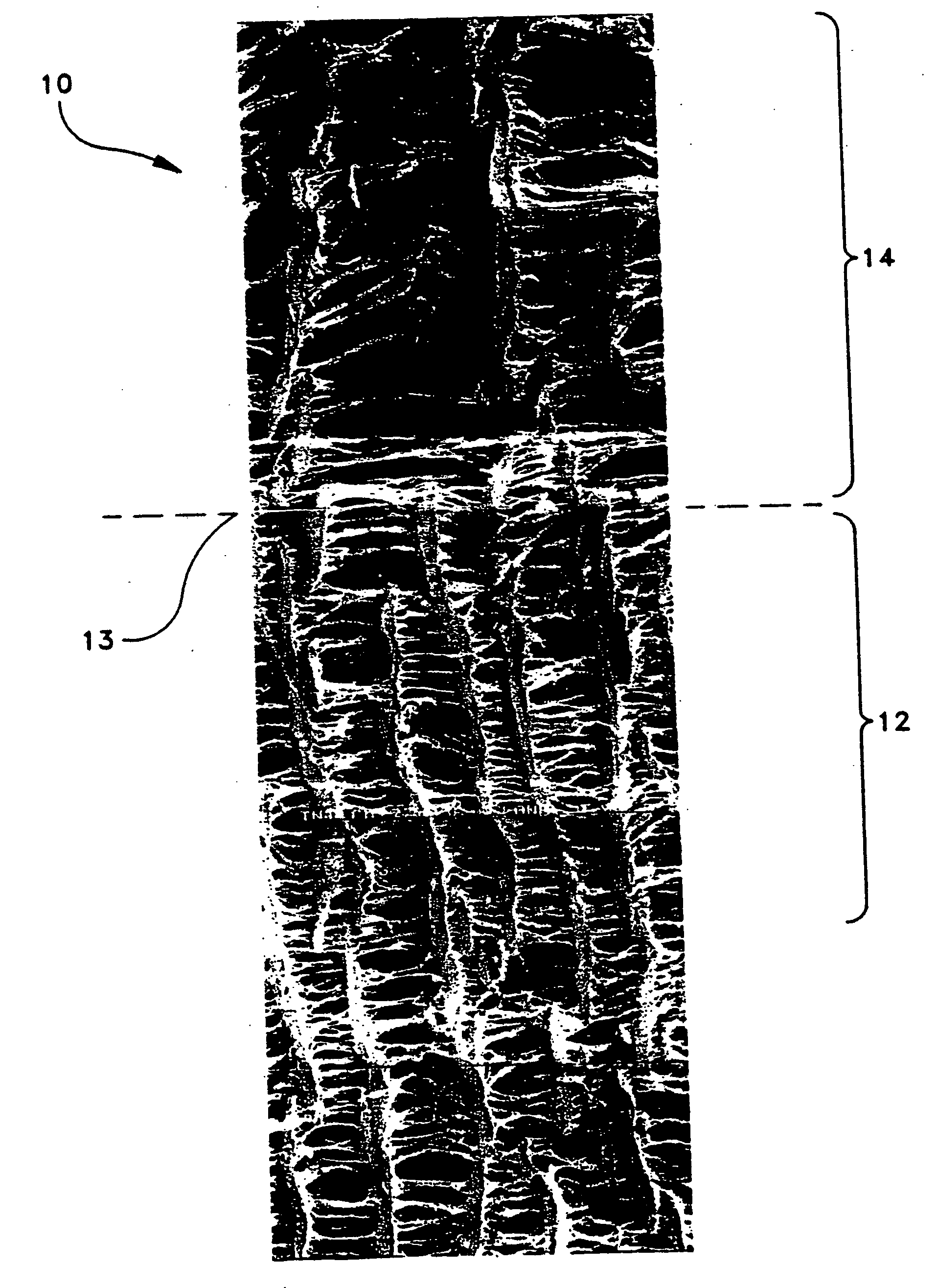
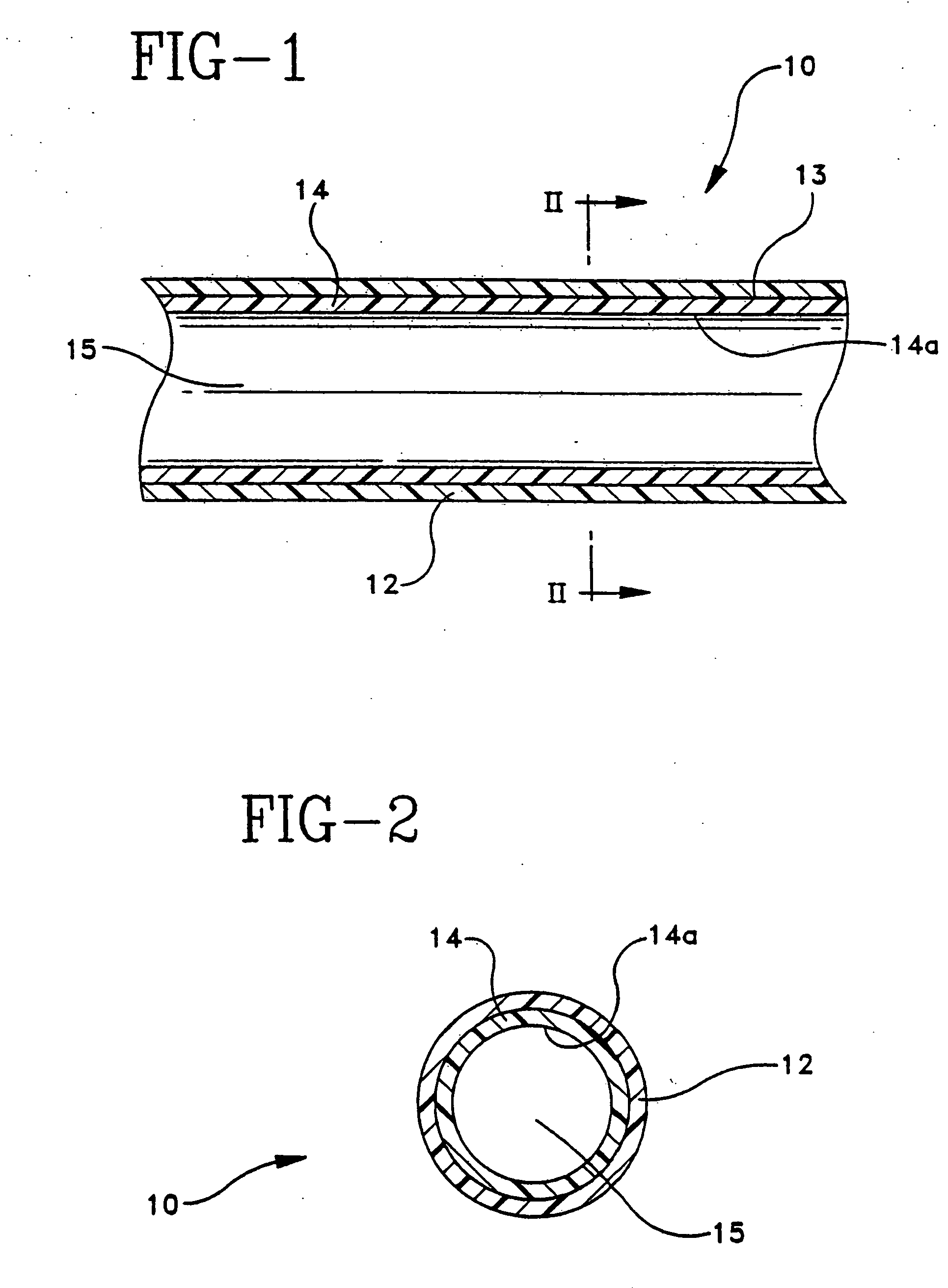
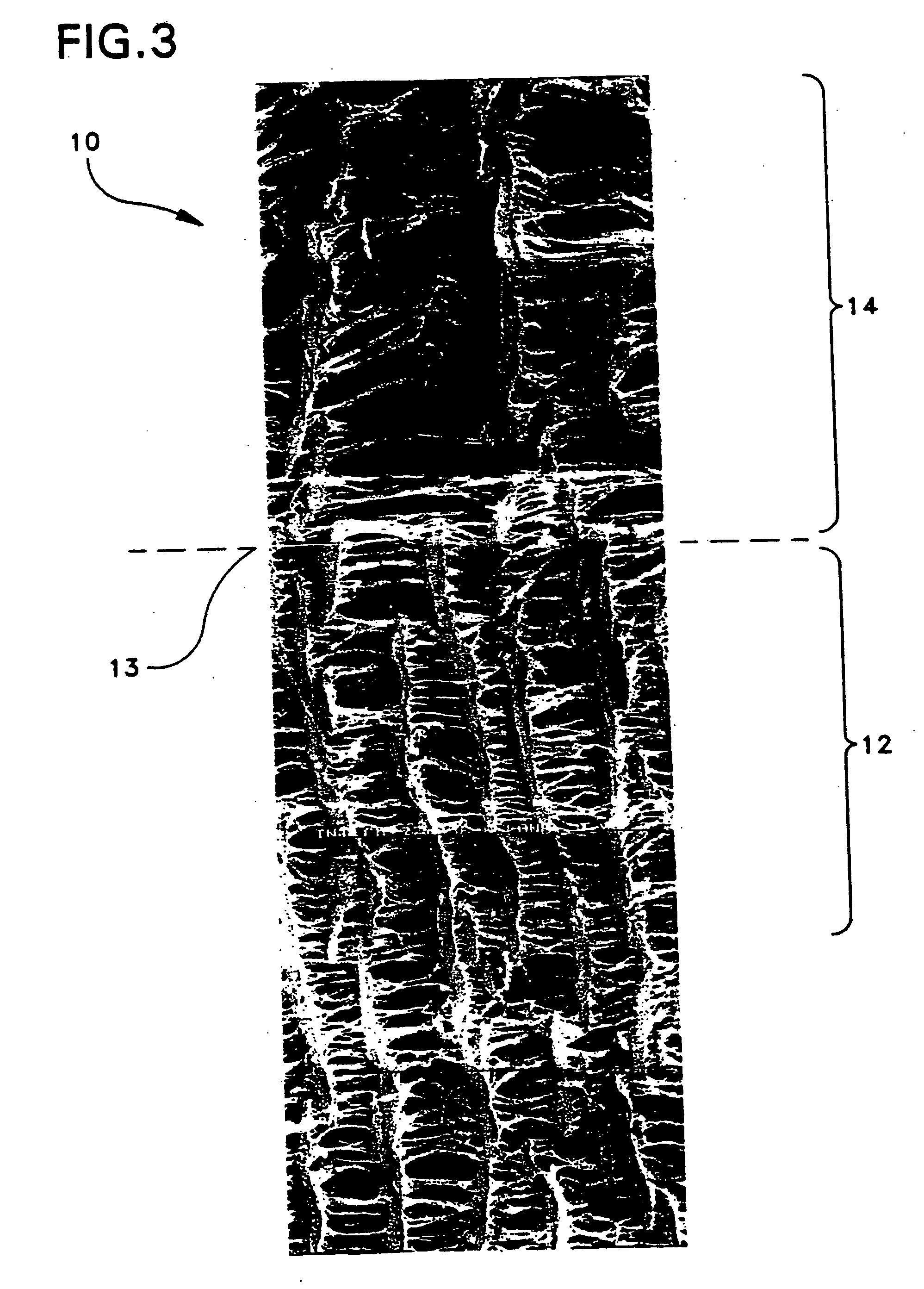
[0060] A thin extruded tube having wall thickness of 0.41 mm and an inner diameter of 6.2 mm was expanded over a stainless steel mandrel at 500.degree. F. to 700% elongation. The ePTFE tube was then sintered at 660.degree. F. for 14 minutes, cooled, and removed from the oven. A second thin extruded tube having wall thickness of 0.45 mm and an inner diameter of 6.9 mm was expanded over the first tube at 500.degree. F. and 400% elongation. The composite was sintered at 660.degree. F. for 14 minutes, cooled, and removed from the oven. The resultant composite tube had a wall thickness of 0.67 mm and an inner diameter of 5.8 mm.

[0061] Table I presents physical property data for a vascular graft of the type depicted in Example I described above. The composite graft was removed from the mandrel and subjected to standard testing of radial tensile strength and suture hole elongation. The radial strength of the 900% / 400% composite graft is equivalent to a single layer 400% elongation graft an...

example 3

[0062] Three composite grafts were constructed and their ability to reseal after a puncture was tested. Graft No. 1 is an ePTFE helically tape-wrapped graft with no resealable layer, and graft Nos. two (2) and three (3) were constructed with a resealable intermediate layer in the below-described procedure.

[0063] Graft No. 1 is an ePTFE graft used as the control in the following experiment. Graft 2 was constructed by first placing an ePTFE tubular structure with an inner diameter of 5 millimeters on a mandrel. A thermoplastic elastomer tubing was then slid over the ePTFE tube. Because of the tackiness of the thermoplastic elastomeric tubing, it was necessary to manipulate the tubing by rolling and stretching it in order to maneuver it over the first ePTFE tubular structure to lie evenly thereon. A second ePTFE tubular structure with an inner diameter of five (5) millimeters was then radially stretched, or expanded to yield an ePTFE tubular structure with an inner diameter of 8 millim...

example 4

[0068] Three additional grafts were constructed with an intermediate resealable layer and tested to determine their ability to seal after puncture.

[0069] Graft No. 4 was made using an ePTFE graft with an initial 5 millimeter inner diameter as the inner tubular structure. The 5 mm ePTFE tube was extruded using a die insert of 0.257 inches, and a mandrel of 0.226 inches. The inner tube was then stretched longitudinally to 500% its original length, and sintered. The inner tube was then stretched radially by placing it on a 5.95 mm mandrel. A pre-sintered PTFE bead-wrap (0.014 inch.+-.0.002 inch diameter, length approximately 30 cm) was then helically wrapped around the exterior of the inner tube at 650 revolutions per minute (RPM), and with a mandrel speed traversely at 800 RPMs. The wrap helically repeated on the tube at approximately every 3.5 cm, and at an angle of approximately 10.degree.-50.degree. with respect to a radial axis. After wrapping, the coil wrapped tube was then heate...


PUM

PropertyMeasurementUnit
elongationaaaaaaaaaa

Abstract

An implantable microporous ePTFE tubular vascular graft exhibits long term patency, superior radial tensile strength and suture hole elongation resistance. The graft includes a first ePTFE tube and a second ePTFE tube circumferentially disposed over the first tube. The first ePTFE tube exhibits a porosity sufficient to promote cell endothelization, tissue ingrowth and healing. The second ePTFE tube exhibits enhanced radial strength in excess of the radial tensile strength of the first tube.

Description

[0001] The present invention relates generally to a tubular implantable prosthesis such as vascular grafts and endoprostheses formed of porous polytetrafluoroethylene. More particularly, the present invention relates to a multi-layered tubular self-sealing graft or endoprosthesis formed from primarily expanded polytetrafluoroethylene.[0002] BACKGROUND OF THE INVENTION[0003] It is well known to use extruded tubes of polytetrafluoroethylene (PTFE) as implantable intraluminal prostheses, particularly vascular grafts. PTFE is particularly suitable as an implantable prosthesis as it exhibits superior biocompatability. PTFE tubes may be used as vascular grafts in the replacement or repair of a blood vessel as PTFE exhibits low thrombogenicity. In vascular applications, the grafts are manufactured from expanded polytetrafluoroethylene (ePTFE) tubes. These tubes have a microporous structure which allows natural tissue ingrowth and cell endothelization once implanted in the vascular system. ...

Claims


Application Information

Patent Timeline
Patent Type & Authority Applications(United States)
IPC IPC(8): A61F2/06A61L27/16A61L27/50A61L27/56
CPCA61F2/06A61L27/16A61L27/507A61L27/56C08L27/18
Inventor LENTZ, DAVIDHENDERSON, JAMIEDORMIER, EDWARDZDRAHALA, RICHARDLOOMIS, GARYRAKOS, RONALDSOWINSKI, KRZYSZTOF
Owner LIFEPORT SCI
Why Eureka
Try Eureka