
Self-expanding pseudo-braided intravascular device

a self-expanding, pseudo-braided technology, applied in the field of self-expanding, knitted devices, can solve the problems of inaccessible many vasculature areas, high patient risk, and narrowing of the vessel, and achieves improved radial strength, high flexibility, and large expansion ratio

Inactive Publication Date: 2010-01-07
ABBOTT CARDIOVASCULAR
View PDF38 Cites 70 Cited by
  • Summary
  • Abstract
  • Description
  • Claims
  • Application Information

AI Technical Summary

Benefits of technology

[0010]Briefly, and in general terms, the present invention provides devices contemplated for the repair of highly tortuous and distal vasculature. Basically, the invention is directed to a self-expanding, pseudo-braided structure that is characterized by having a large expansion ratio and high flexibility as well as an improved radial strength accomplished through the advantageous utilization of deflection energy.
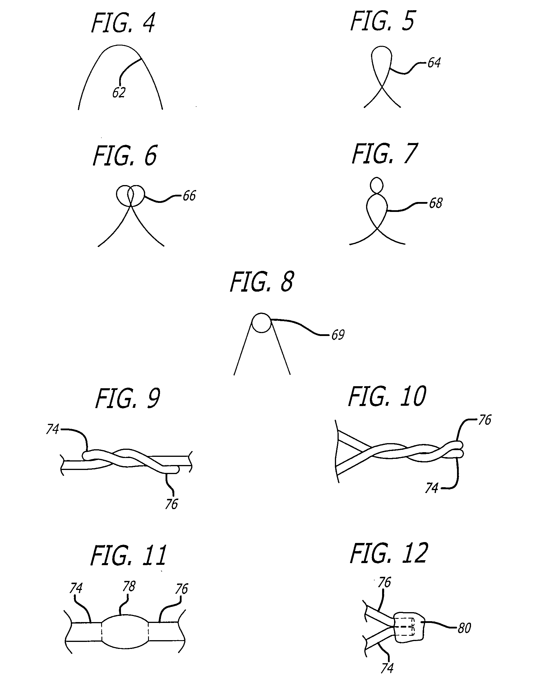
[0013]In other aspects of the invention, there are various methods for terminating the filaments. Additionally, various methods are contemplated for adjusting the radiopacity as well as the expansion and spring characteristics of the pseudo-braided devices. Various methods are also contemplated for improving coverage of the pseudo-braided devices and enhancing the anchoring of the same within distal and tortuous vasculature.

Problems solved by technology

Vessel walls can weaken and become distended over time in response to blood flow and pressures, thereby resulting in formation of aneurysms.
Such narrowing of the vessel is, of course, highly dangerous to the patient where the afflicted vessel provides the sole blood flow access to critical parts of the body.
Due to procedures such as thrombectomies or due to the natural, albeit undesirable, function of a patient's vasculature, emboli may be found traveling through a blood vessel.
Embolic material can cause unwanted blockages or otherwise facilitate the formation of an occlusion in a vessel which too, can be highly dangerous to a patient.
Unfortunately, many areas of vasculature are inaccessible by a conventional intravascular repair means because the repair devices typically employed are often too large or rigid to be effectively advanced through tortuous vasculature or to vasculature that is very distal to the site through which the vasculature is accessed.
Moreover, conventional devices can lack a profile suited to avoid traumatic engagement with a vessel wall or sufficient radiopacity so that remote observation is impossible.
Thus, where an intravascular approach is not available to the physician, invasive surgical techniques must be applied.

Method used


Image

  • Self-expanding pseudo-braided intravascular device
  • Self-expanding pseudo-braided intravascular device
  • Self-expanding pseudo-braided intravascular device

Examples


Embodiment Construction

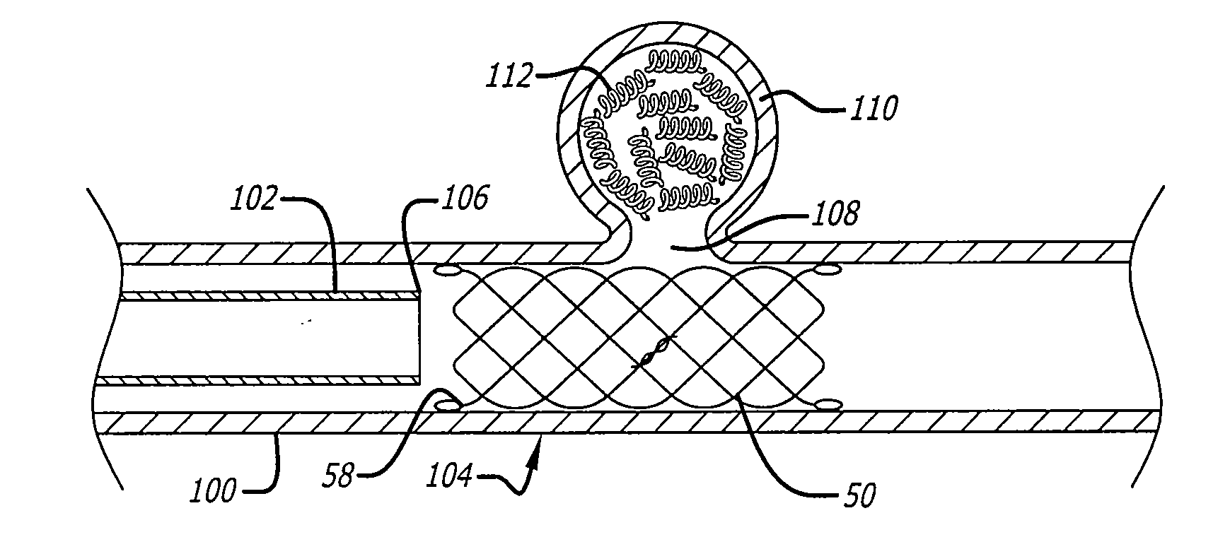
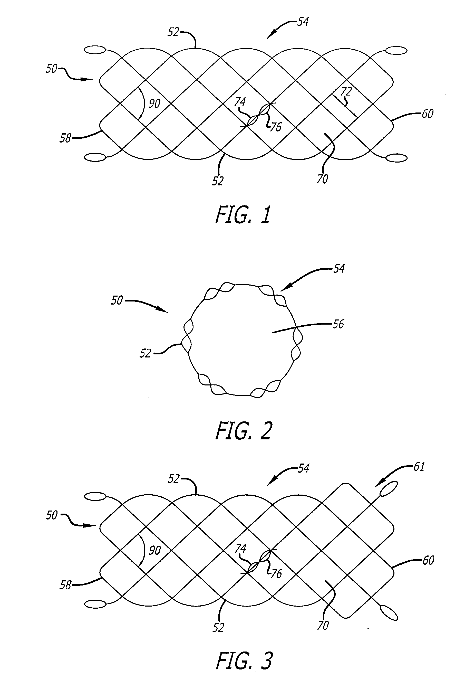
[0045]Turning now to the drawings, and particularly to FIGS. 1 and 2, there is shown a self-expanding pseudo-braided structure 50 of the present invention. The pseudo-braided device 50 is contemplated for use in highly tortuous and very distal vasculature of an animal or human. Due to its novel structure, the pseudo-braided device 50 is flexible in a compressed configuration and conformable to tortuous anatomy in a relaxed condition. Moreover, the device embodies high flexibility and a large expansion capability while providing sufficient radial force (i.e., hoop stiffness).

[0046]In a presently preferred embodiment, the pseudo-braided device 50 of the present invention is formed from the single filament 52. The filament 52 is configured into a repeating helical pattern that is interlaced upon itself by passing the end of the filament over then under the filament forming the helix as the end of the filament is wound down and back up the length of the structure to thereby form a gener...


PUM


Abstract

A self-expanding, pseudo-braided device embodying a high expansion ratio and flexibility as well as comformability and improved radial force. The pseudo-braided device is particularly suited for advancement through and deployment within highly tortuous and very distal vasculature. Various forms of the pseudo-braided device are adapted for the repair of aneurysms and stenoses as well as for use in thrombectomies and embolic protection therapy.

Description

BACKGROUND OF THE INVENTION[0001]The present invention relates to self-expanding, knitted devices and more particularly, to a self-expanding knitted device for intravascular repair of distal and tortuous vasculature.[0002]The vasculature of an animal or a human characteristically suffers from a variety of maladies. Vessel walls can weaken and become distended over time in response to blood flow and pressures, thereby resulting in formation of aneurysms. Such aneurysms can take on a myriad of forms. In particular, aneurysms may form at or near bifurcated vessels creating enlarged areas about the bifurcation, or may form a pocket, for example, in side walls of vessels. Due to the complications associated with aneurysms that rupture or otherwise fail, it is critical that an aneurysm be treated expeditiously and effectively. Intravascular treatment procedures include placing grafts within the aneurysm in a manner to ensure that blood flows through the graft rather than through the weake...

Claims


Application Information

Patent Timeline
Patent Type & Authority Applications(United States)
IPC IPC(8): A61F2/06A61B17/12A61F2/90
CPCA61B17/12022A61B17/12118A61B17/1214A61B17/12172D10B2509/06A61F2/90D04C1/06D04C3/48D04C7/00A61B2017/1205
Inventor HANCOCK, DAVIDBROWN, PETER S.VOSS, LARRY
Owner ABBOTT CARDIOVASCULAR
Learn More