Lifting cradle head based on ball screw

A ball screw and pan/tilt technology, applied in machine/stand, supporting machine, mechanical equipment, etc., can solve the problems of complex installation, lack of lifting pan/tilt, single structure, etc. Simple to use effects

Pending Publication Date: 2018-05-08
SOUTH CHINA UNIV OF TECH
View PDF6 Cites 6 Cited by
  • Summary
  • Abstract
  • Description
  • Claims
  • Application Information

AI Technical Summary

Problems solved by technology

But there are still deficiencies in it, its structure is single, and the device is slightly complicated
Moreover, there is still a lack of elevating heads based on ball screws in the field of parabolic robots.

Method used


Image

  • Lifting cradle head based on ball screw
  • Lifting cradle head based on ball screw

Examples


Embodiment Construction

[0022] In order to better understand the present invention, the present invention will be further described below in conjunction with the accompanying drawings and specific embodiments.

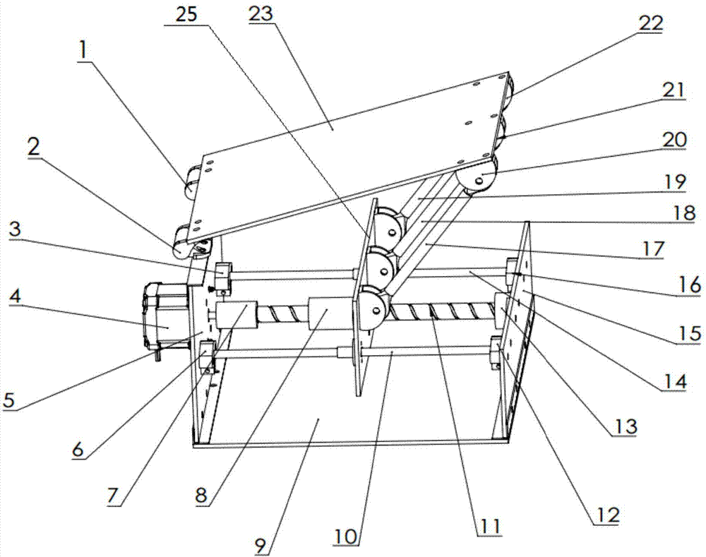
[0023] Such as figure 1 Shown, a kind of elevating platform based on ball screw, comprises support, the ball screw 11 that is arranged on the support and guide rod, the screw bearing 8 that cooperates with described ball screw 11, and described Flange bearings, support rods, lower plates 25, upper plates 23, and stepping motors 4 that guide rods are slidably fitted. 5. The vertical plate 15, the bottom plate 9, and the motor fixing plate 5 are fixedly connected by corner codes. The stepping motor 4 is fixed on the motor fixing plate 5, one end of the ball screw 11 is fixedly connected with the output shaft of the stepping motor 4 through a coupling 7, and the other end is connected to the screw base 13, and the ball screw 11 The bar base 13 is fixed on the vertical plate 15, and the two end...


PUM


Abstract

The invention discloses a lifting cradle head based on a ball screw. The lifting cradle head comprises a support, the ball screw and a guide rod which are arranged on the support, a lead screw bearingmatched with the ball screw, a flange bearing in sliding fit with the guide rod, supporting rods, a lower plate, an upper plate and a stepping motor; the stepping motor is fixed on the support and isin driving connection with the ball screw; the lower plate is fixedly connected with the lead screw bearing and the flange bearing; one ends of the supporting rods are movably hinged to one end of the lower plate, and the other ends of the supporting rods are movably hinged to one end of one the upper plate; and the other end of the upper plate is movably hinged to one end of the support. According to the lifting cradle head, the ball screw and the stepping motor are combined to use so that the angle can be accurately adjusted; according to driving the stepping motor, pitching can be realizedby controlling the motor; and the lifting cradle head has the advantages that operation and structure are simple, the bearing force is large, the telescopic ratio is large, the occupied space is small, and a simple, practicable, fast and reliable pitch angle adjusting process can be realized on an object throwing robot.

Description

technical field [0001] The invention relates to a pan-tilt device, in particular to a lifting pan-tilt based on a ball screw, which is mainly used for adjusting the pitch angle of a parabolic robot. Background technique [0002] At present, there have been very fruitful efforts in the existing and previous technical requirements on the lifting head in the market, and many excellent technical solutions have also been designed. For example, the application number CN201420745723.X and publication number CN204312966U filed by Beijing Aerospace Fudao High-Tech Co., Ltd. on December 2, 2014 is the technology adopted by the device named "A Liftable Pan-Tilt Device". plan. But wherein still have deficiency, its structure is single, and device is slightly complicated. And, the elevating head based on ball screw in the field of parabolic robot still lacks at present. Contents of the invention [0003] The technical problem to be solved by the present invention is how to realize a...

Claims


Application Information

Patent Timeline
Patent Type & Authority Applications(China)
IPC IPC(8): F16M11/10F16M11/18F16M11/22
CPCF16M11/10F16M11/18F16M11/2021F16M11/22
Inventor 张东黄金豪林城杨镇坡吴伟锋陈之楷
Owner SOUTH CHINA UNIV OF TECH
Why Eureka
Try Eureka