

Slide block type multistage coupling parallel mechanism
A slider-type, parallel technology, applied in the field of robotics, can solve the problems of multi-stage hybrid mechanism, insufficient working space, and difficult actual control, etc., to improve stiffness, reduce quantity, and increase local degrees of freedom Effect
- Summary
- Abstract
- Description
- Claims
- Application Information
AI Technical Summary
Problems solved by technology
Method used
Image

Examples
Embodiment 1
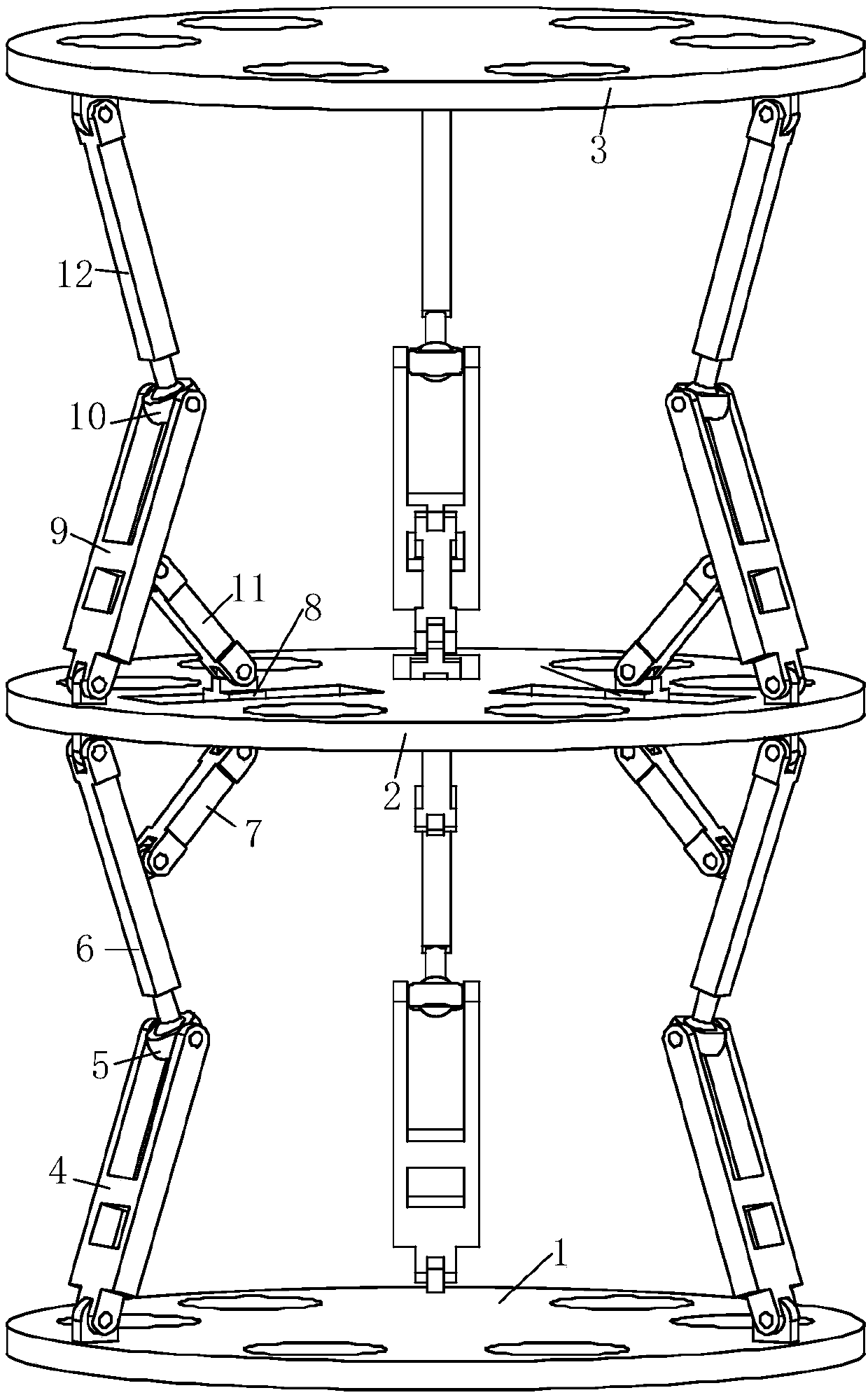
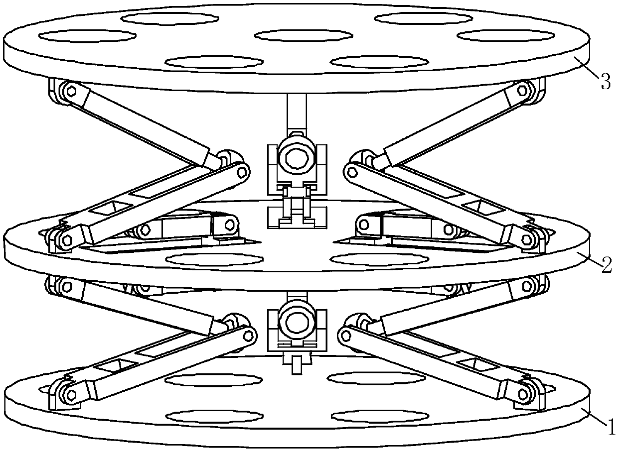
[0024] exist figure 1 , figure 2 , image 3 In the schematic diagram of the slider-type multi-stage coupling parallel mechanism shown, one end of the first active rod 4 in the three branch chains with the same structure connecting the fixed platform 1 and the coupling platform 2 is connected to the fixed platform through a rotating pair. The other end of the rod is provided with a first ball bowl 5 connected by a rotating pair, and is connected with one end of the first driven rod 6 through a spherical pair, and the other end of the first driven rod is connected to the lower surface of the coupling platform through a rotating pair connection, three evenly distributed chutes are arranged on the coupling platform, and slide blocks 8 are arranged in the chute, and one end of the first connecting rod 7 is connected with the middle part of the first driven rod through a rotating pair, and the first connecting rod The other end is connected with the lower surface of the slider th...
Embodiment 2
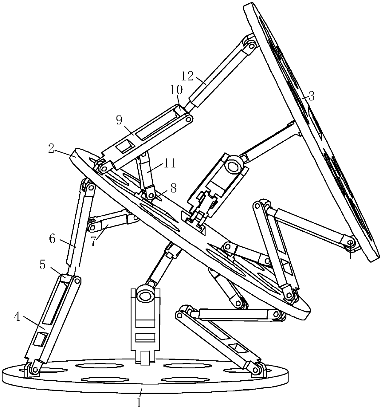
[0029] Such as Figure 4 , Figure 5 and Figure 6 As shown, in the three branch chains connecting the fixed platform 1, the coupling platform 2 and the moving platform 3, two of them have the same structure, and their components and connection methods are the same as those of the branch chains in Example 1. The other branch chains One end of the first active rod 4 is connected with the fixed platform through the rotating pair, and its other end is connected with one end of the first driven rod 6 through the rotating pair, and the other end of the first driven rod is connected with the lower surface of the coupling platform through the rotating pair Connected, one end of the first connecting rod 7 is connected with the middle part of the first driven rod through a rotating pair, and the other end of the first connecting rod is connected with the lower surface of the slider 8 provided in the chute through a rotating pair; the second active One end of the rod 9 is connected wi...
PUM
 Abstract
Description
Claims
Application Information