Gear type multi-level coupling parallel mechanism

A gear-type, parallel technology, applied in the field of robotics, can solve problems such as the difficulty of kinematics positive and negative solutions, reduce the dynamic characteristics of the mechanism, and increase the volume of the upper-level drive, so as to reduce the number of drives, reduce the number, and increase the expansion ratio. Effect

Pending Publication Date: 2018-04-20
YANSHAN UNIV
View PDF0 Cites 0 Cited by
  • Summary
  • Abstract
  • Description
  • Claims
  • Application Information

AI Technical Summary

Problems solved by technology

However, most of the hybrid mechanisms have the problem that the lower-level drive becomes the load of the upper-level drive, which greatly reduces the dynamic characteristics of the mechanism, and at the same time increases the volume of the upper-level drive. After multiple stages are connected in series, the structure becomes very bloated and loses practical significance.
Moreover, with the increase in the number of parallel joints in the hybrid mechanism, the kinematics forward and reverse solution becomes more and more difficult, and the driving becomes very difficult.

Method used


Image

  • Gear type multi-level coupling parallel mechanism
  • Gear type multi-level coupling parallel mechanism
  • Gear type multi-level coupling parallel mechanism

Examples


Embodiment 1

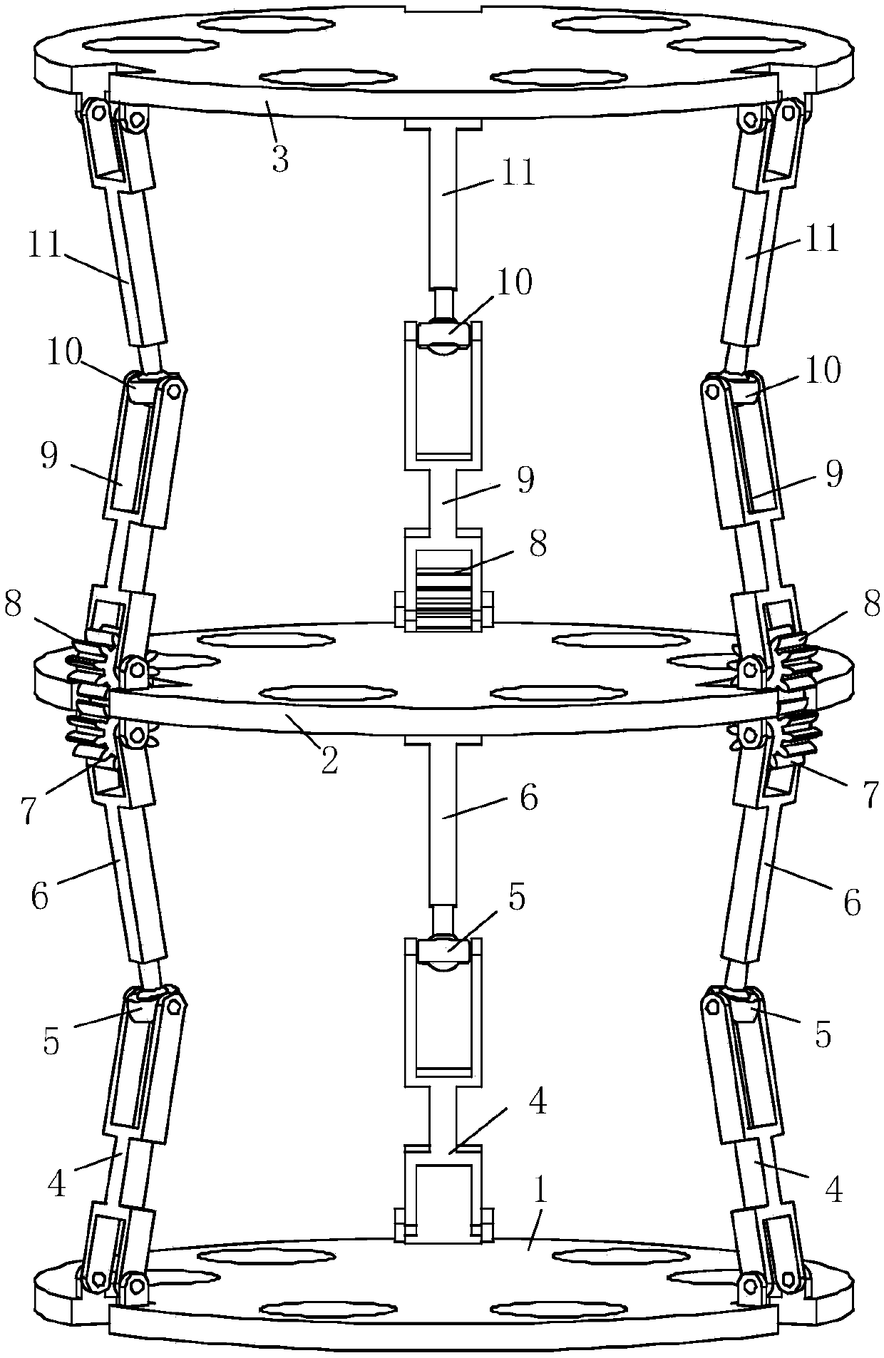
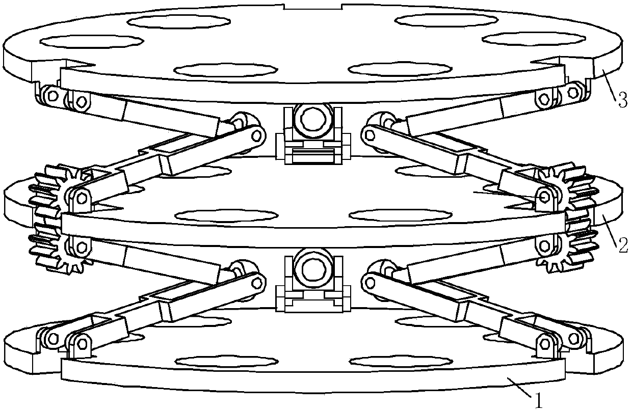
[0026] exist figure 1 , figure 2 and image 3 In the schematic diagram of the gear-type multi-stage coupling parallel mechanism shown, there are three evenly distributed opening slots on the fixed platform 1, the coupling platform 2 and the moving platform 3, and these three platforms are connected by three kinematic branch chains with the same structure. One end of the active rod 4 in the motion branch chain is connected with the fixed platform through the rotating pair arranged on the opening groove of the fixed platform, and the other end of the active rod is provided with a ball bowl 5 connected through the rotating pair, and is connected with the driven wheel through the spherical pair. One end of the rod 6 is connected, and the other end of the driven rod is rotationally connected with the first spur gear 7 through a rotating pair arranged on the lower surface of the coupling platform, and the second spur gear 8 is rotated through the rotating pair arranged on the uppe...

Embodiment 2

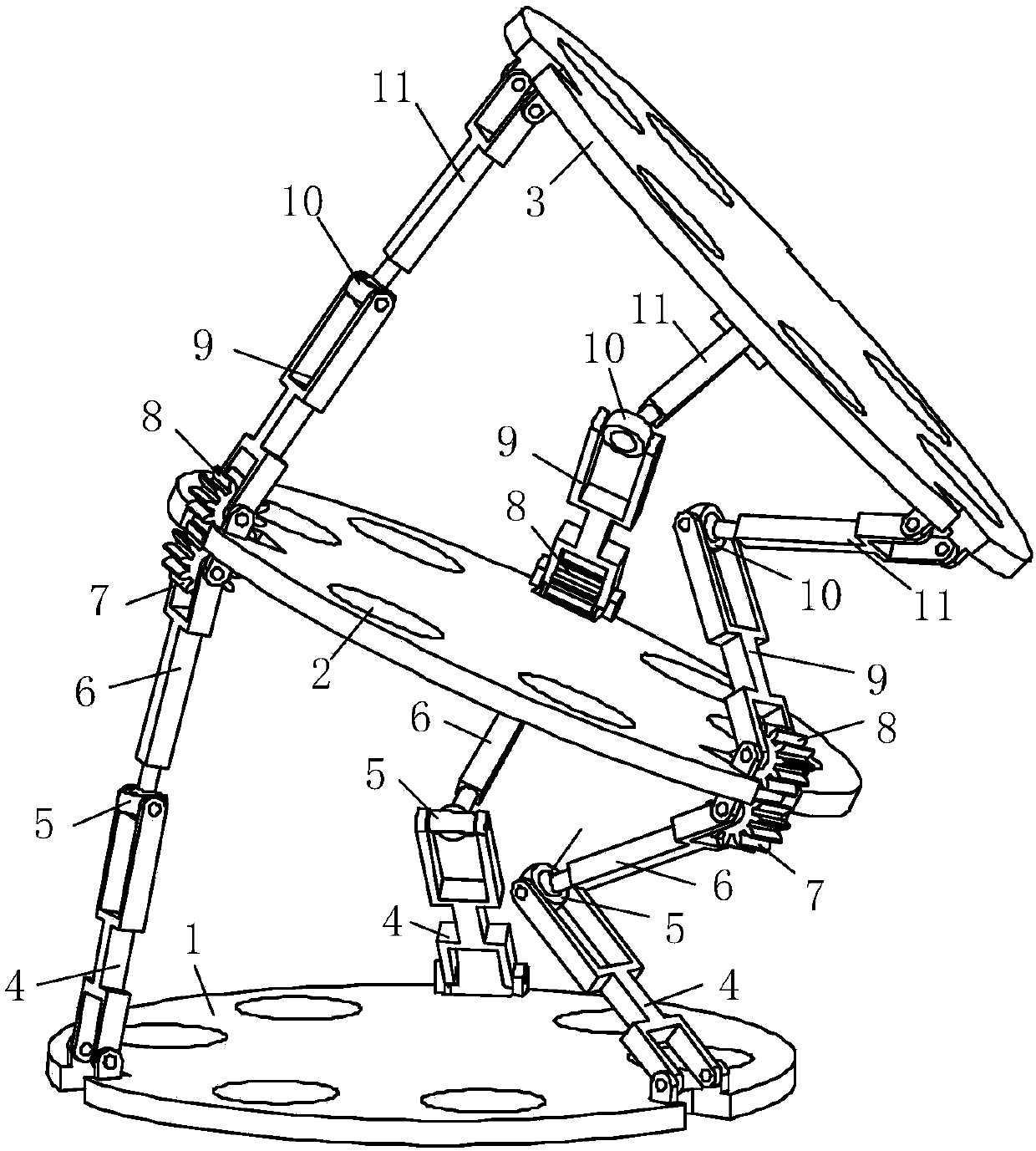
[0029] Such as Figure 4 , Figure 5 and Figure 6 As shown, there are three evenly distributed opening slots on the fixed platform 1, the coupling platform 2 and the moving platform 3, and among the three kinematic branch chains connecting the three platforms, two kinematic branch chains have the same structure. The components and connection method are the same as those in Embodiment 1. One end of the active rod 4 in the other branch chain is connected with the fixed platform through the rotating pair arranged on the opening groove of the fixed platform, and the other end of the active rod is connected with the driven rod through the rotating pair. 6, the other end of the driven rod is connected to the first spur gear 7 through a rotating pair on the lower surface of the coupling platform, and the second spur gear 8 is connected through the rotating pair on the upper surface of the coupling platform. Rotately connected with one end of another driving rod 9, the meshing mode...


PUM


Abstract

A gear-type multi-stage coupling parallel mechanism, which includes a fixed platform, a coupling platform, a moving platform, and three motion branch chains with the same structure connecting the three platforms, wherein the fixed platform, the coupling platform and the moving platform are provided with three uniformly distributed The two ends of the active rod in each motion branch chain are respectively connected with the fixed platform and one end of the driven rod, and the other end of the driven rod is connected with the first spur gear in rotation, and the second spur gear The cylindrical gear is rotationally connected to one end of the other driving rod, the meshing mode of the first gear and the second gear is external meshing, the other end of the driving rod is connected to one end of the other driven rod, and the other end of the driven rod is connected to the mobile platform connection. The invention has a large working space, greatly reduces the number of drive units, and the kinematics positive and negative solutions become extremely simple, which is very beneficial to the control work in engineering practice.

Description

technical field [0001] The invention belongs to the field of robots, in particular to a parallel mechanism. Background technique [0002] Although the parallel mechanism has the advantages of high rigidity, high precision, and good dynamic performance, due to the interference of kinematic pairs and branch chains, and the influence of space singularity, the common shortcoming of the small working space of the parallel mechanism restricts the application level of the parallel mechanism. Many scholars try to adopt the method of simple series connection between multiple parallel mechanisms through a shared platform, that is, the method of hybrid connection, which aims to solve the problem of not only retaining the advantages of parallel mechanisms, but also making up for the lack of working space. In theory, this method does have a significant effect on improving the working space of the parallel mechanism. However, since this connection method requires the installation of power...

Claims


Application Information

Patent Timeline
Patent Type & Authority Applications(China)
IPC IPC(8): B25J9/00
CPCB25J9/0045
Inventor 周玉林刘扬李会芹谢运涛曹琛
Owner YANSHAN UNIV
Why Eureka
Try Eureka