Modified guidewire for left ventricular access lead

a technology of guidewires and lead electrodes, which is applied in the field of implantation and placement of cardiac leads, can solve the problems of not being able to advance further into the vascular system using standard techniques and equipment, not being able to achieve the optimal position of the lead electrode, and reducing friction. , the effect of reducing the risk

Inactive Publication Date: 2006-08-08
CARDIAC PACEMAKERS INC
View PDF6 Cites 102 Cited by
  • Summary
  • Abstract
  • Description
  • Claims
  • Application Information

AI Technical Summary

Benefits of technology

[0009]Because the lead has a somewhat greater stiffness property than its associated guidewire, there are greater frictional forces between the lead and the vessel in which it is placed than between the guidewire and the wall of the lead body defining the lead's lumen. Hence, the guidewire can be removed from the lead without dragging the lead with it.
[0011]In accordance with a second embodiment of the present invention, there is provided a guidewire comprised of at least three zones. Each zone differs from the other two in terms of its stiffness and flexibility. Each zone also has geometric characteristics which assist in proper placement of the lead and further assist in preventing dislodgement of the lead as the guide catheter is extracted and as the guidewire itself is extracted.
[0012]Specifically, the first and most distal zone is intended to be very floppy to prevent trauma to the surrounding vessel walls when the guidewire is being advanced beyond the distal end of a guide catheter when deploying a coronary vein lead. This distal zone may include a spiral wound portion surrounding a thin, solid ribbon core and a spherical tip. The second zone is relatively more stiff than its adjacent distal section and may comprise a solid wire or spiral wound wire having a cross-sectional diameter that does not exceed the cross-sectional diameter of the first zone. The second and most proximal zone is preferably of a larger diameter and is somewhat stiffer than the first zone but not as stiff and flexible as the lead body in which it is inserted. The second zone comprises a wire or hypo tube which can be manipulated to apply advancement forces during deployment of the lead and stabilizing forces to a lead during extraction of the guide catheter. A diametric transition between the first and second zones is abrupt and ideally corresponds to a matching feature in the lead so that this transition is the point where most of the advancement forces and counter forces are transmitted to the lead.
[0013]In a third embodiment, a finishing wire is provided which has a squared end for engaging a portion of the lead to hold it in place during guide catheter removal. The guide catheter easily disengages from the lead for withdrawal of the finishing wire.
[0017]Other improvements also exist. For example, the improved guidewire (or portions thereof) can be provided with a hydrophilic coating to produce a highly lubricious surface. The presence of such a surface reduces friction between the lumen wall of the lead and the guidewire thereby reducing the risk that the lead will be dislodged during extraction of the guidewire.

Problems solved by technology

Placement of cardiac leads in the distal branches of the coronary venous system, the great cardiac vein, or the coronary sinus is a difficult task.
Often when deploying the lead there comes a point at which the lead cannot be advanced further into the vascular system using standard techniques and equipment.
All too often this point is not the optimal position for the lead's electrode, either for sensing cardiac electrical activity or delivering pacing therapy to the heart.
There are several reasons which make proper placement of the lead difficult.
While stiffer guidewires offer additional support, they may impede advancement due to their relative size with respect to the lumen of the lead.
Additionally, when proper placement of the lead is achieved, problems arise during guide catheter or guidewire extraction.
All too often, the act of extracting the guide catheter and / or guidewire causes the lead to be dislodged from the implanted position.
Standard guidewires and stylets are not suitable for maintaining position while the guide catheter is removed due to insufficient stiffness, lack of appropriate force transmission features, and friction between the guidewire and lumen wall of the coronary vein lead.

Method used


Image

  • Modified guidewire for left ventricular access lead
  • Modified guidewire for left ventricular access lead
  • Modified guidewire for left ventricular access lead

Examples


Embodiment Construction

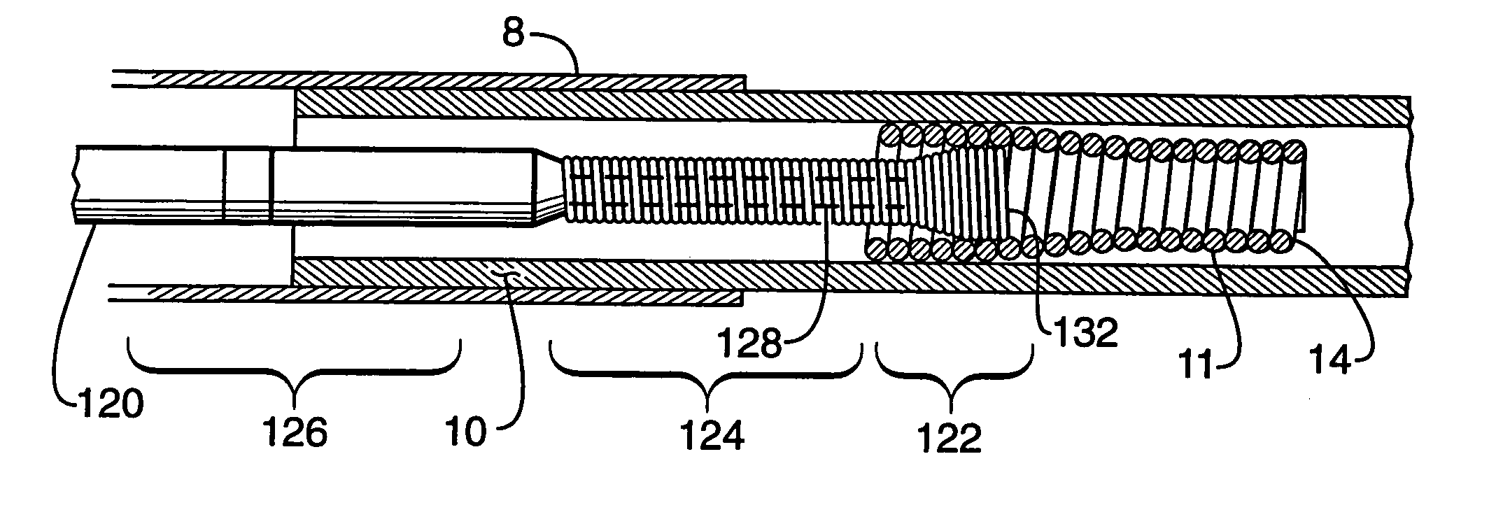
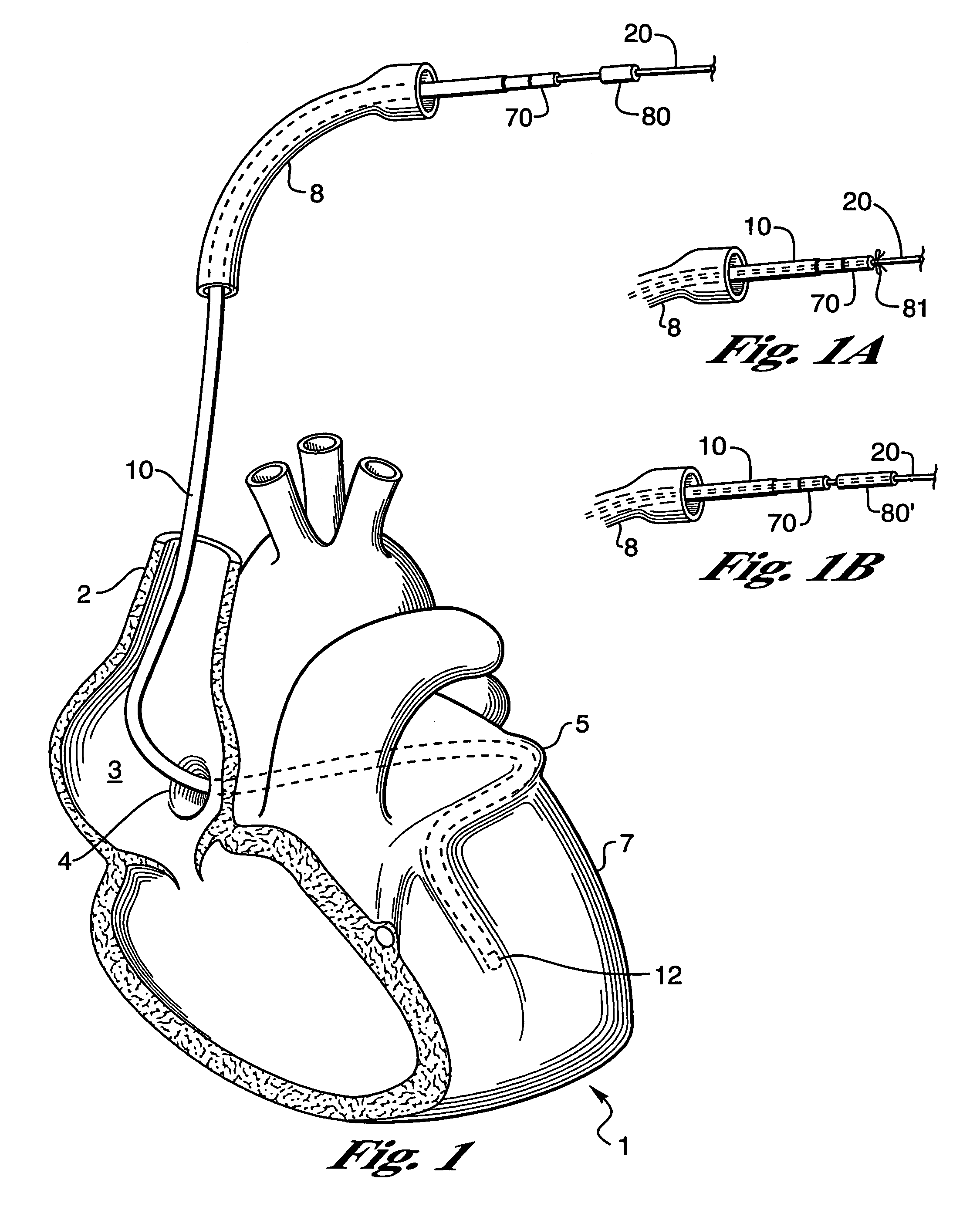
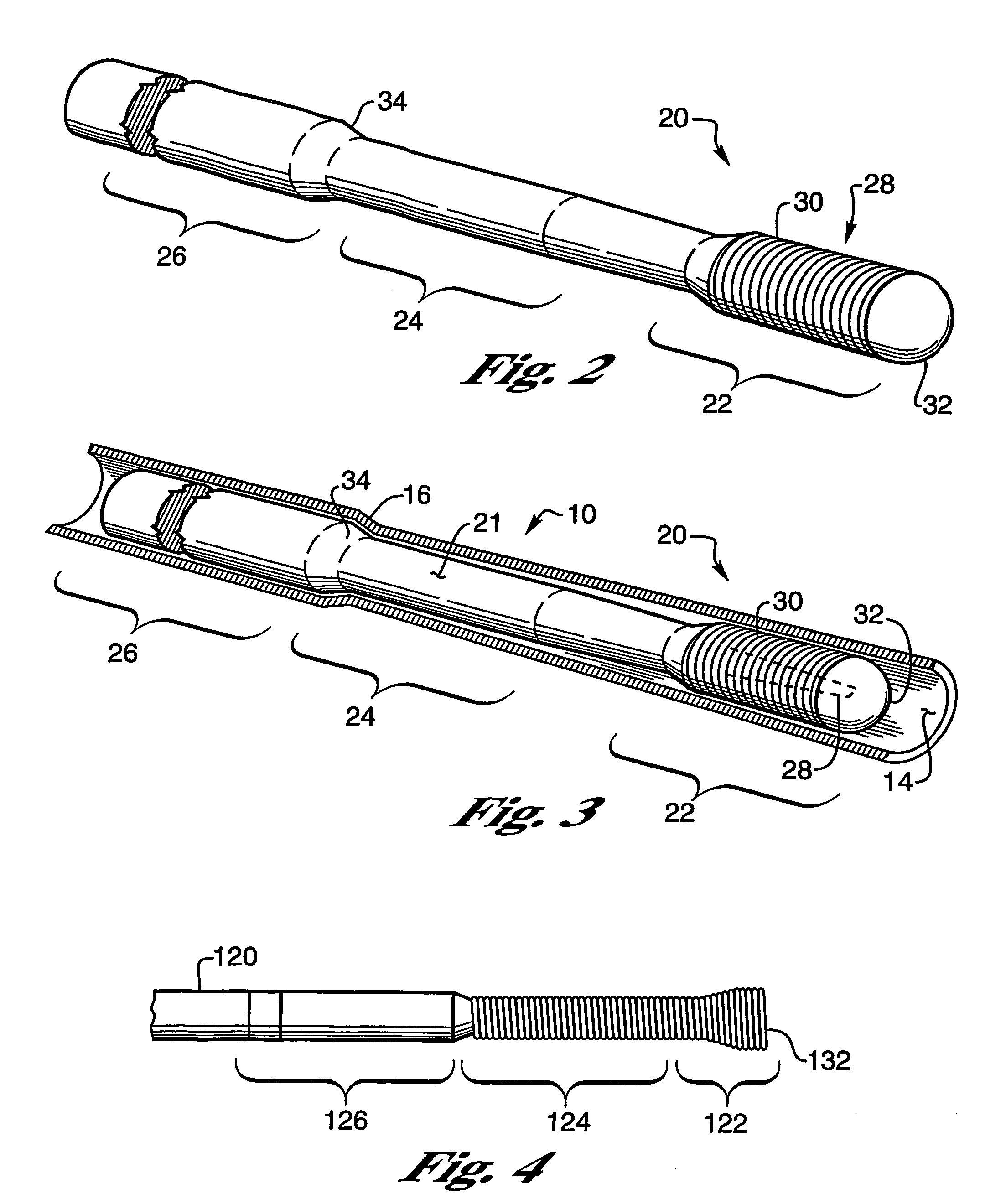
[0031]FIG. 1 shows a human heart 1 with a coronary lead 10 passing through the superior vena cava 2, the right atrium 3, and the coronary sinus 4 into the great vein 5 of the heart 1 so that an electrode 12 on the lead 10 is properly positioned in a branch of the coronary vein on the left sides of the heart. When positioned as shown, the electrode 12 can be used to either sense the electrical activity of the heart or to apply stimulating pulses to the left ventricle 7 without the electrode being positioned within the left ventricular chamber. A portion of a guide catheter 8 is used to insert the lead into the heart 1. The present invention is concerned with guidewires and / or finishing wires useful for placing leads 10 and their electrodes in the vasculature and for removing the associated guide catheter 8 and a guidewire 20 without dislodging the leads 10 and its electrode(s) 12. As used herein, the term “guidewires” includes both the guidewires used to install the leads and “finish...


PUM


Abstract

An improved guidewire for assisting in implantation of a cardiac lead includes three sections. The most distal zone is sufficiently floppy to prevent trauma to the vessel walls through which the guidewire and lead are inserted. An intermediate zone is generally stiffer and has a cross-section less than or equal to the cross-section of the distal zone. The third zone is stiffer yet and is joined to the intermediate zone by a shoulder. The shoulder cooperates with protrusions on the lead to transfer forces between the guidewire and lead. A finishing wire having temporary locking means to lock the finishing wire to the lead is employed to remove the guide catheter without moving the lead from its desired location. Lubricious coatings are also provided to reduce friction between the lead and guidewire.

Description

[0001]This is a continuation of application Ser. No. 10 / 081,436, filed Feb. 20, 2002, U.S. Pat. No. 6,671,560, which is a continuation of application Ser. No. 09 / 466,266, filed Dec. 17, 1999, now U.S. Pat. No. 6,356,791, which is a continuation-in-part of application Ser. No. 09 / 164,891, filed Oct. 1, 1998, now abandoned, which is a continuation-in-part of application Ser. No. 09 / 097,101, filed Jun. 12, 1998, now abandoned.BACKGROUND OF THE INVENTION[0002]I. Field of the Invention[0003]The invention relates to the implantation and placement of cardiac leads used in combination with cardiac rhythm management devices, e.g., heart pacemakers or defibrillators, to monitor and control the rhythm of the heart. This invention is more particularly directed toward a guidewire / pacing lead configuration adapted to assist in the implantation and placement of a cardiac lead having one or more electrodes that are to reside in the distal branches of the coronary venous system, the great cardiac ve...

Claims


Application Information

Patent Timeline
Patent Type & Authority Patents(United States)
IPC IPC(8): A61N1/05A61M25/09
CPCA61M25/09A61N1/057A61B2017/22035A61N2001/0578A61M2025/09175
Inventor WESTLUND, RANDY W.TOCKMAN, BRUCE A.PETERFESO, RANDALL M.GREENLAND, JOHN S.HINDERS, MARY N.
Owner CARDIAC PACEMAKERS INC
Why Eureka
Try Eureka