Capacitor discharge engine ignition device

Active Publication Date: 2009-05-21
MAHLE INT GMBH
View PDF9 Cites 7 Cited by
  • Summary
  • Abstract
  • Description
  • Claims
  • Application Information

AI Technical Summary

Benefits of technology

[0028]As described above, according to the present invention, the space is formed between the ignition coil and the exciter coil to reduce mutual inductance between the primary coil of the ignition coil and the exciter coil, and the magnetic flux generated from the exciter coil when the charges in the ignition capacitor discharge through the primary coil of the ignition coil is prevented from acting to prevent a change in magnetic flux interlinking with the ignition coil, thereby preventing a reduction in high voltage for ignition induced in the secondary coil of the ignition coil.
[0029]Also according to the present invention, the plurality of ignition coil connection terminals drawn out from the ignition coil

Problems solved by technology

In the conventional engine ignition device, a plurality of terminals drawn out from the exciter coil and the ignition coil are provided in different positions axially of the coil unit, which makes troublesome an operation of inserting the plurality of terminals into holes in a circuit board, and inevitably reduces assembly operation efficiency of the device.
Also, when the plurality of

Method used


Image

  • Capacitor discharge engine ignition device
  • Capacitor discharge engine ignition device
  • Capacitor discharge engine ignition device

Examples


Example

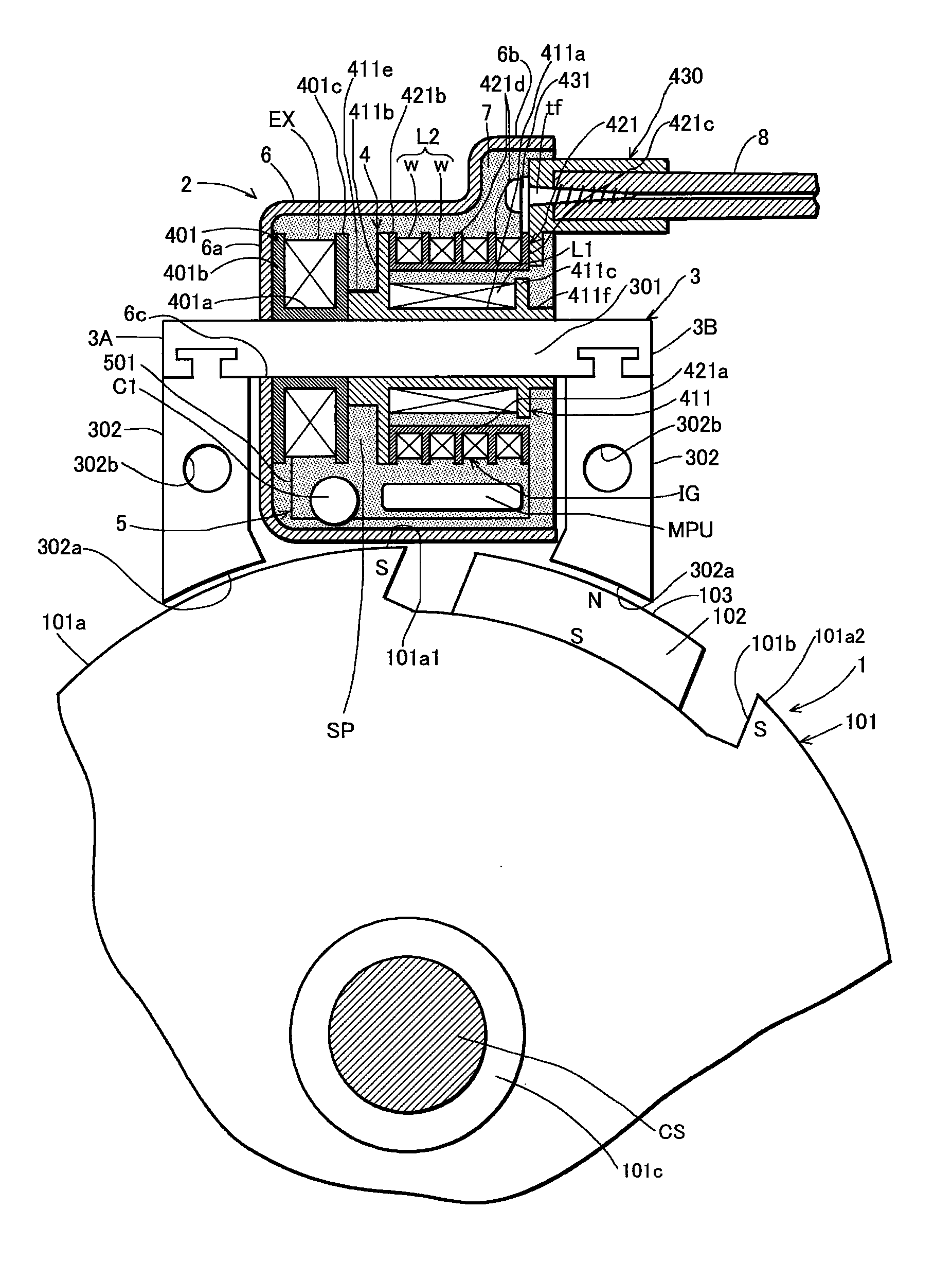
[0038]In FIG. 1, a reference numeral 1 denotes an outer magnet type magneto rotor that is mounted to a crankshaft of an unshown engine and cooperates with an ignition device according to the present invention, and 2 denotes the ignition device according to the present invention.

[0039]The magneto rotor 1 is comprised of a flywheel 101 made of ferromagnetic material such as iron and having a cylindrical outer peripheral surface 101a, and an arcuate permanent magnet 102 mounted in a recess 101b formed in the outer peripheral surface of the flywheel 101. The permanent magnet 102 is magnetized so that a magnetizing direction is a radial direction of the flywheel 101. In the shown example, a magnetic pole surface on a radially outer periphery of the permanent magnet 102 is a north pole, and south poles of the magnet are led out to outer peripheral surfaces 101a1 and 101a2 of the flywheel near opposite ends of the recess 101b facing circumferentially of the flywheel. The magnetic pole (nor...


PUM


Abstract

A capacitor discharge ignition device in which a coil unit including an ignition coil and an exciter coil wound around a common core, and an ignition unit including a circuit board and components of an ignition circuit mounted to the circuit board are housed in a case and molded with resin poured into the case, wherein the ignition coil and the exciter coil are placed axially with a spacing therebetween and a space is formed between the coils, the circuit board of the ignition unit is placed on a lateral side of the coil unit, and terminals for connecting the ignition coil and the exciter coil to the circuit board are all connected to the circuit board through the space between the ignition coil and the exciter coil.

Description

TECHNICAL FIELD OF THE INVENTION[0001]The present invention relates to a capacitor discharge engine ignition device.PRIOR ART OF THE INVENTION[0002]An ignition device of an engine is comprised of an ignition coil, and an ignition unit that controls a current to flow through a primary coil of the ignition coil so as to induce a high voltage for ignition in a secondary coil thereof at ignition timing of the engine. The ignition device of the engine needs to have weatherization, and generally, as disclosed in Japanese Patent Application Laid-Open Publication No. 2002-161843, an ignition coil and an ignition unit are housed in a case and are molded with resin poured into the case.[0003]A capacitor discharge engine ignition device includes an ignition coil, an ignition power supply portion, an ignition capacitor provided on a primary side of the ignition coil, a capacitor charging circuit that charges the ignition capacitor with an output of the ignition power supply portion, a discharge...

Claims


Application Information

Patent Timeline
IPC IPC(8): F02P5/00
CPCF02P1/005F02P3/08F02P1/086
Inventor SUGIYAMA, MASAYUKIHATANO, YASUKAZUSHIMOYAMA, AKIRA
Owner MAHLE INT GMBH
Why Eureka
Try Eureka