Filter and duplexer

a duplexer and filter technology, applied in the direction of impedence networks, electrical apparatus, piezoelectric/electrostrictive/magnetostrictive devices, etc., can solve the problems of difficult to produce small-sized or thin devices, difficult to produce small-sized or thin portable terminals, etc., to reduce mutual inductance, reduce the effect of mutual inductance and high suppression

Active Publication Date: 2007-11-22
TAIYO YUDEN KK
View PDF9 Cites 7 Cited by
  • Summary
  • Abstract
  • Description
  • Claims
  • Application Information

AI Technical Summary

Benefits of technology

[0011]A more specific object of the present invention is to provide a filter and a duplexer that can reduce the mutual inductance between signal lines, and have a high degree of suppression in the stop band, even if the size is made smaller.

Problems solved by technology

A dielectric duplexer is large in size, and with a dielectric duplexer, it is very difficult to produce a small-sized or thin portable terminal.
Also, where a surface acoustic wave device is used on one side, it is difficult to produce a small-sized or thin device, due to the size of the dielectric device.

Method used


Image

  • Filter and duplexer
  • Filter and duplexer
  • Filter and duplexer

Examples


first embodiment

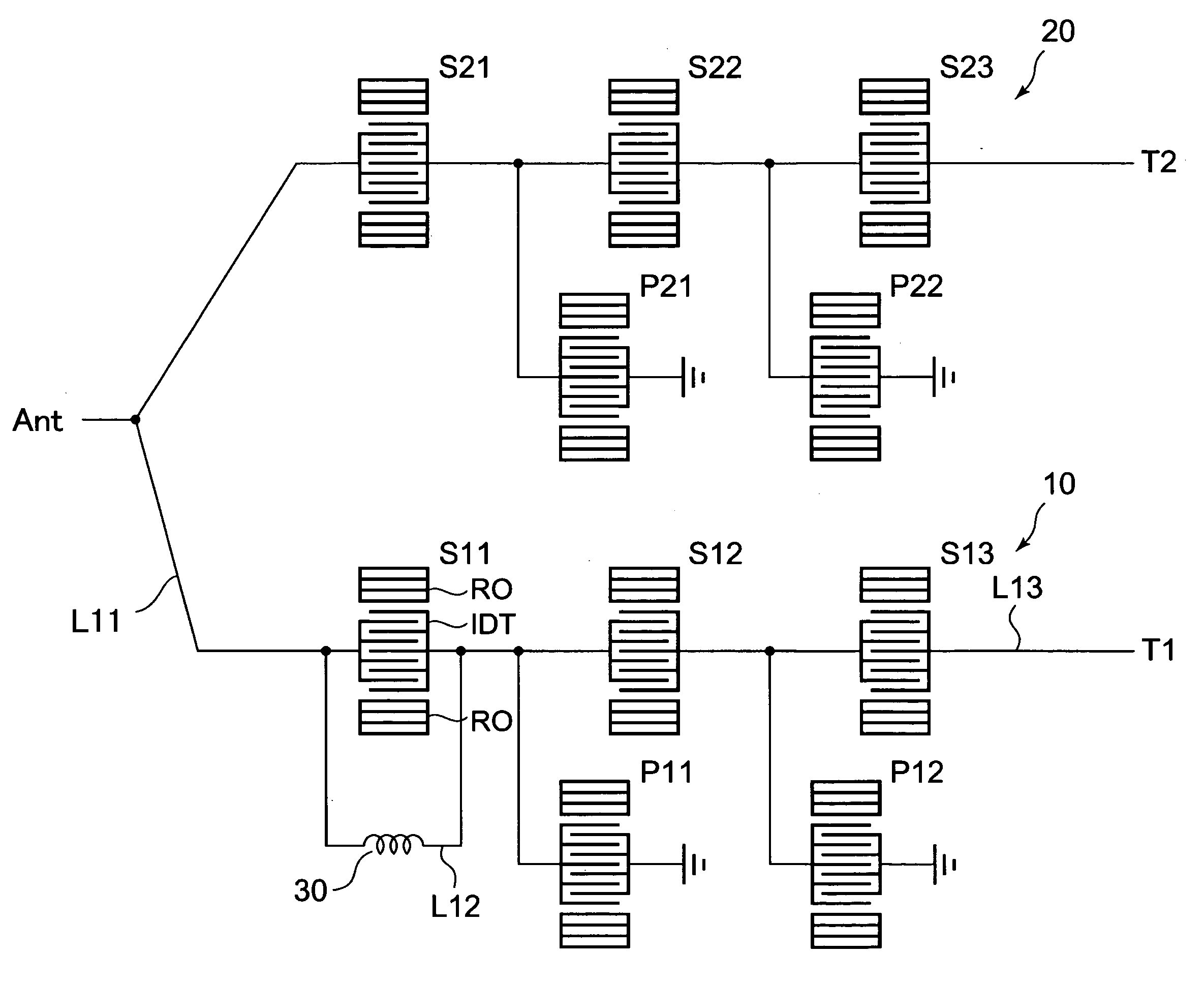
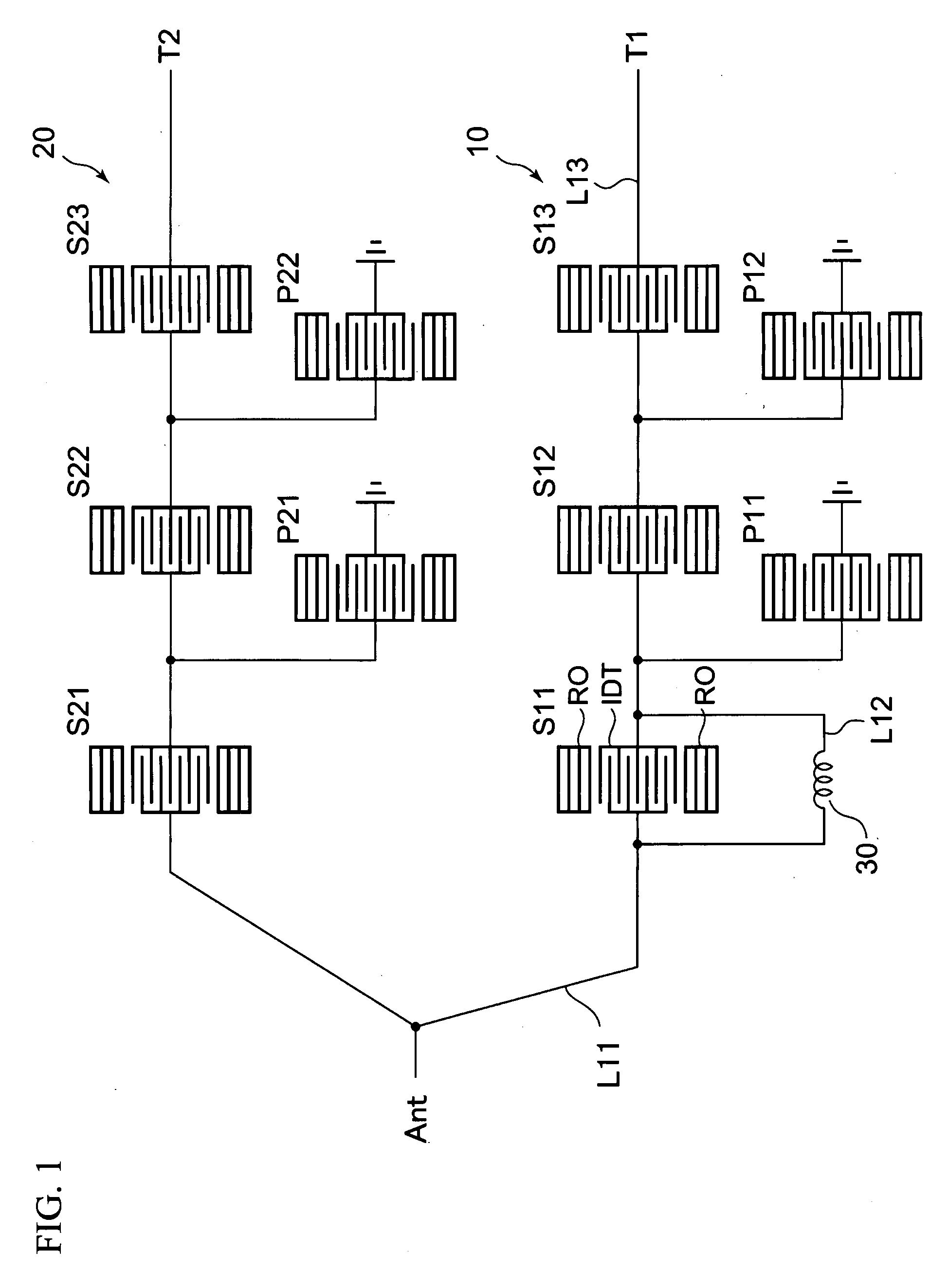
[0045]A first embodiment of the present invention is an example where a duplexer for 2-GHz band W-CDMA systems having ladder filters is mounted on a stacked package. In this embodiment, a first filter 10 having a first inductor 30 connected in parallel to series-arm resonators serves as a reception filter, and a second filter 20 serves as a transmission filter. FIG. 1 is a circuit diagram of a duplexer in accordance with the first embodiment. As shown in FIG. 1, the first filter 10 (a reception filter) is connected between a common terminal Ant (an antenna terminal) and a first terminal T1 (a reception terminal). The second filter 20 (a transmission filter) is connected between the common terminal Ant and a second terminal T2 (a transmission terminal). The first filter 10 is a ladder filter, and includes series-arm resonators S11 through S13 and parallel-arm resonators P11 and P12. The second filter 20 is also a ladder filter, and includes series-arm resonators S21 through S23, and ...

second embodiment

[0060]A second embodiment is an example where the directions of the currents flowing through the common line L11 and the first terminal line L13 are also at 90 degrees with respect to each other, as well as the directions of the currents flowing through the first inductor line L12 and the first terminal line L13. FIG. 10A is a plan view showing the surface of the die-attach layer 44 of Comparative Example 1, and is the same drawings a FIG. 7A. FIG. 10B is a plan view of the surface of the die-attach layer 44 of a duplexer in accordance with the second embodiment. The other stacked layers are the same as those of the first embodiment, and explanation of them is omitted here. The die-attach layer 44 of this embodiment differs from the die-attach layer 44 of the first embodiment shown in FIG. 7B in that the directions of the currents flowing through the common line L11 and the first terminal line L13 are substantially at 90 degrees with respect to each other, as well as the directions ...

third embodiment

[0063]As shown in FIG. 12, a third embodiment of the present invention is an example case where a first filter 10a having a first inductor 30a connected in parallel to a series-arm resonator is used as a transmission filter, and a second filter 20a is used as a reception filter. A first terminal T1 serves as a transmission terminal, and a second terminal T2 serves as a reception terminal. The series-arm resonators S11 through S13 and the parallel-arm resonators P11 and P12 of the first filter 10a (the transmission filter) are formed in a first filter chip 11a. The series-arm resonators S21 through S23 and the parallel-arm resonators P21 and P22 of the second filter 20a (the reception filter) are formed in a second filter chip 21a. The first inductor 30a is formed in an inductor chip 31a. A common line L11 connects a common terminal Ant and the first filter 10a. A first inductor line L12 connects the first inductor 30a and the series-arm resonator S11. A first terminal line T13 conne...


PUM


Abstract

A duplexer includes: a first filter that is connected to a common terminal and a first terminal, and includes a first series-arm resonator; a second filter that is connected to the common terminal and a second terminal; a first inductor that is connected in parallel to the first series-arm resonator; a mounting unit that has the first filter and the second filter mounted thereon; a first inductor line that is provided on the mounting unit, and connects the first inductor and the first series-arm resonator; and a first terminal line that is provided on the mounting unit, and connects the first filter and the first terminal. In this duplexer, the directions of currents flowing through the first inductor line and the first terminal line cross each other.

Description

BACKGROUND OF THE INVENTION[0001]1. Field of the Invention[0002]The present invention generally relates to a filter and a duplexer, and more particularly, to a filter and a duplexer that are mounted on a mounting unit.[0003]2. Description of the Related Art[0004]As mobile communication systems have been developed dramatically in recent years, portable telephone devices, portable information terminals, and the likes have rapidly spread, and such terminals with smaller sizes and higher performances are being developed. Also, analog systems and digital systems are both used in portable telephone systems, and the frequencies mostly used are in the 800 MHz to 1 GHz band and the 1.5 GHz to 2.0 GHz band. Antenna duplexers utilizing surface acoustic wave filters or piezoelectric thin-film filters have also been developed for the use in those devices designed for mobile communications.[0005]In the recent development of portable telephone devices, the performances of the terminals have been i...

Claims


Application Information

Patent Timeline
Patent Type & Authority Applications(United States)
IPC IPC(8): H03H9/70
CPCH03H9/725H03H9/46
Inventor IWAMOTO, YASUHIDEINOUE, SHOGOUEDA, MASANORIMITOBE, SEIICHI
Owner TAIYO YUDEN KK
Why Eureka
Try Eureka