Apparatus for docking a printed circuit board

a printed circuit board and accurately installed technology, applied in the direction of coupling device connection, coupling parts engagement/disengagement, instruments, etc., can solve the problems of difficult to achieve the mechanical advantage of accurately and carefully docking an electronic circuit board, and damaged printed circuit boards such as daughter cards

Active Publication Date: 2008-04-29
LENOVO GLOBAL TECH INT LTD
View PDF27 Cites 42 Cited by
  • Summary
  • Abstract
  • Description
  • Claims
  • Application Information

AI Technical Summary

Benefits of technology

[0012]The foregoing and other objects, features and advantages of the invention will be apparent from the following more particular description of a preferred embodiment of the invention, as illustrated in accompanying drawings wherein like reference numbers represent like parts of the invention.

Problems solved by technology

However, computer components are often installed in configurations making it difficult to achieve the mechanical advantage to accurately and carefully dock an electronic circuit board.
Printed circuit boards, such as daughter cards, can become damaged during insertion into a connector or header due to an uneven application of force or misalignment of the daughter card with the connector slot.

Method used


Image

  • Apparatus for docking a printed circuit board
  • Apparatus for docking a printed circuit board
  • Apparatus for docking a printed circuit board

Examples


Embodiment Construction

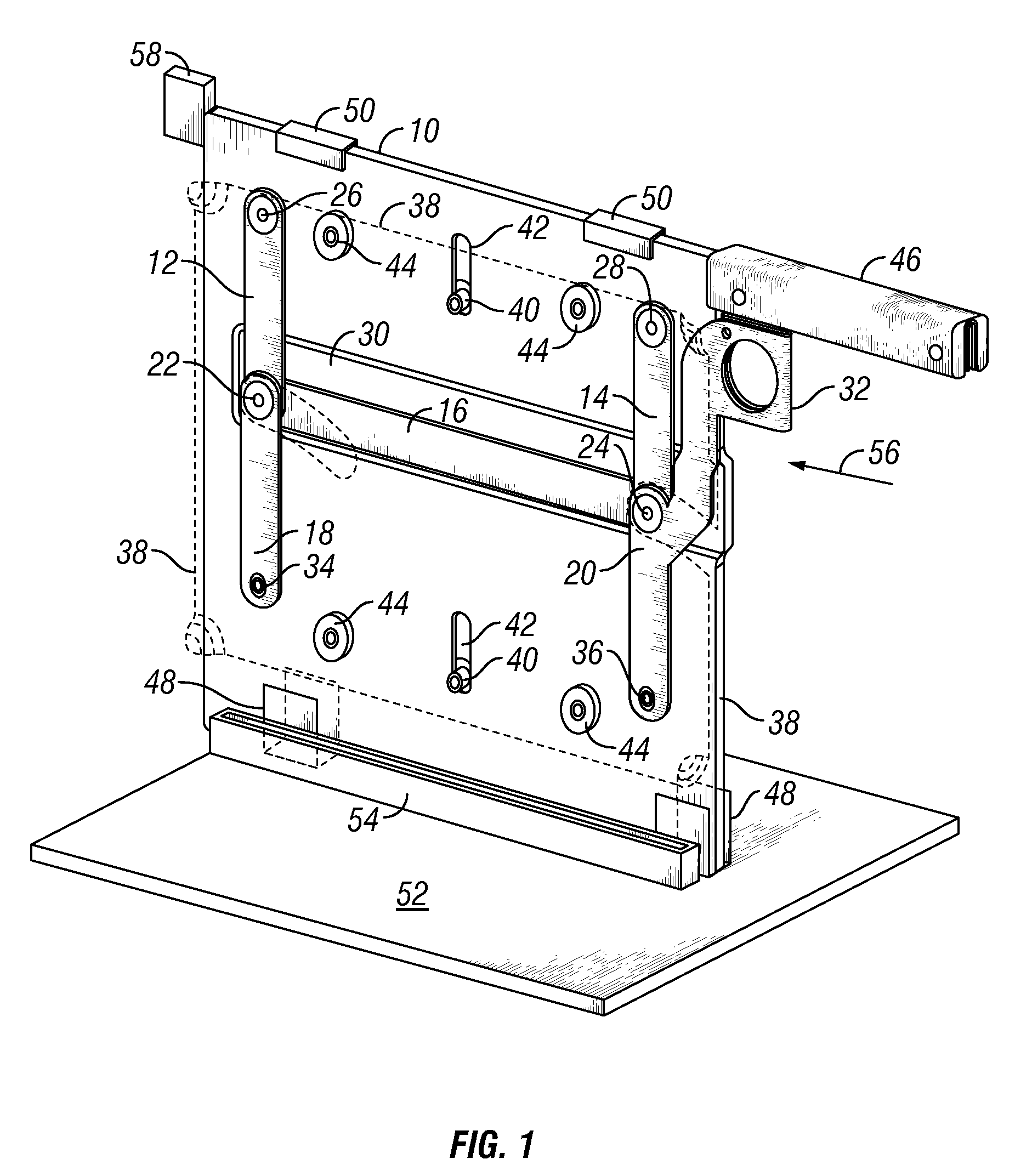
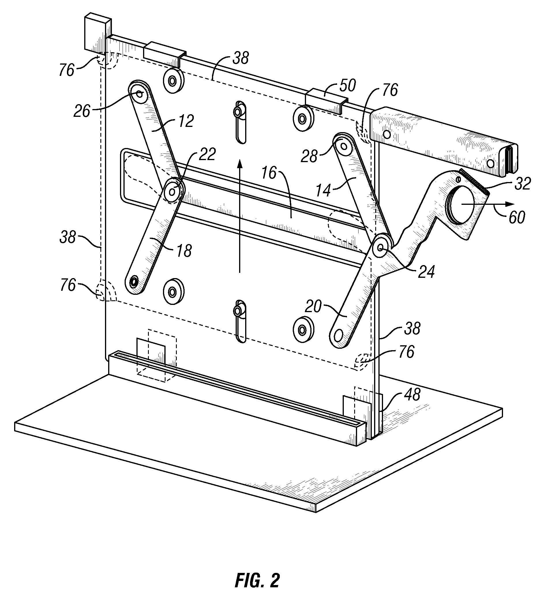
[0016]FIG. 1 is a perspective view of a guide plate 10 and a parallelogram linkage in accordance with one embodiment of the invention. The parallelogram linkage is comprised of a plurality of pivot arms 12, 14, a link arm 16, and two positioning arms 18, 20. The arms are pivotally coupled to each other at the pivot junctions 22, 24 and pivotally coupled to the guide plate 10 at the pivot couplings 26, 28. The arms are preferably made of a rigid material, such as metal, to maintain its rigidity in both tension and compression.

[0017]The link arm 16 is of a sufficient length to maintain the pivot arms 12, 14, which have the same length, in a generally parallel configuration. Since the arms cannot all lie in the same plane at the pivot junctions 22, 24, the guide plate 10 may include an indented region 30 to accommodate the link arm 16 behind the pivot arms 12, 14. The positioning arms 18, 20 are shown in front of the pivot arms 12, 14 so that the positioning arms are a spaced a short d...


PUM


Abstract

An apparatus to align and dock or undock a first electronic circuit board with a first connector with a second electronic circuit board with a second connector. The apparatus comprises a guide plate with a linkage to connect to a mounting plate. The first electronic circuit board is secured to the mounting plate. The guide plate is inserted into a chassis comprising a guide to receive the guide plate. The guide aligns the first connector to be received in the second connector. The linkage is actuated by displacing a positioning handle. The linkage translates the motion in a direction generally perpendicular to the direction of displacement of the positioning handle. The mounting plate is translated in the generally perpendicular direction, and the first connector is received into the second connector. The operation may be reversed to remove the first connector from the second connector.

Description

BACKGROUND OF THE INVENTION[0001]1. Field of the Invention[0002]The present invention relates to printed circuit board installation in electronic devices. More specifically, the invention provides an apparatus for accurately docking a printed circuit board in a constrained space.[0003]2. Description of the Related Art[0004]Swappable components have become commonplace in computer systems. Computer systems often use swappable memory, hard drives, and various pieces of hardware commonly referred to as daughter cards. Many maintenance, repair, or upgrade operations may involve the removal of a piece of hardware, or the insertion of a piece of hardware, or both while the computer is on and functioning.[0005]In a server rack, or chassis, many computer components are stored in close proximity. Often, these racks have numerous electronic circuit boards. The electronic circuit boards may be aligned in banks, both above or below, or beside each other. The electronic circuit boards may provide...

Claims


Application Information

Patent Timeline
Patent Type & Authority Patents(United States)
IPC IPC(8): H01R13/62
CPCG06F1/186H05K7/1415
Inventor DESROSIERS, NORMAN BRUCEHERRING, DEAN FREDERICKWORMSBECHER, PAUL ANDREW
Owner LENOVO GLOBAL TECH INT LTD
Why Eureka
Try Eureka