Two component seal

a seal and two-part technology, applied in the field of pin seals, can solve problems such as wear and the need for replacemen

Active Publication Date: 2008-05-06
DOOSAN BOBCAT NORTH AMERICA INC
View PDF30 Cites 28 Cited by
  • Summary
  • Abstract
  • Description
  • Claims
  • Application Information

AI Technical Summary

Problems solved by technology

Excessive introduction of dirt in the pivoting parts causes wear and the need for replacement.

Method used


Image

  • Two component seal
  • Two component seal
  • Two component seal

Examples


Embodiment Construction

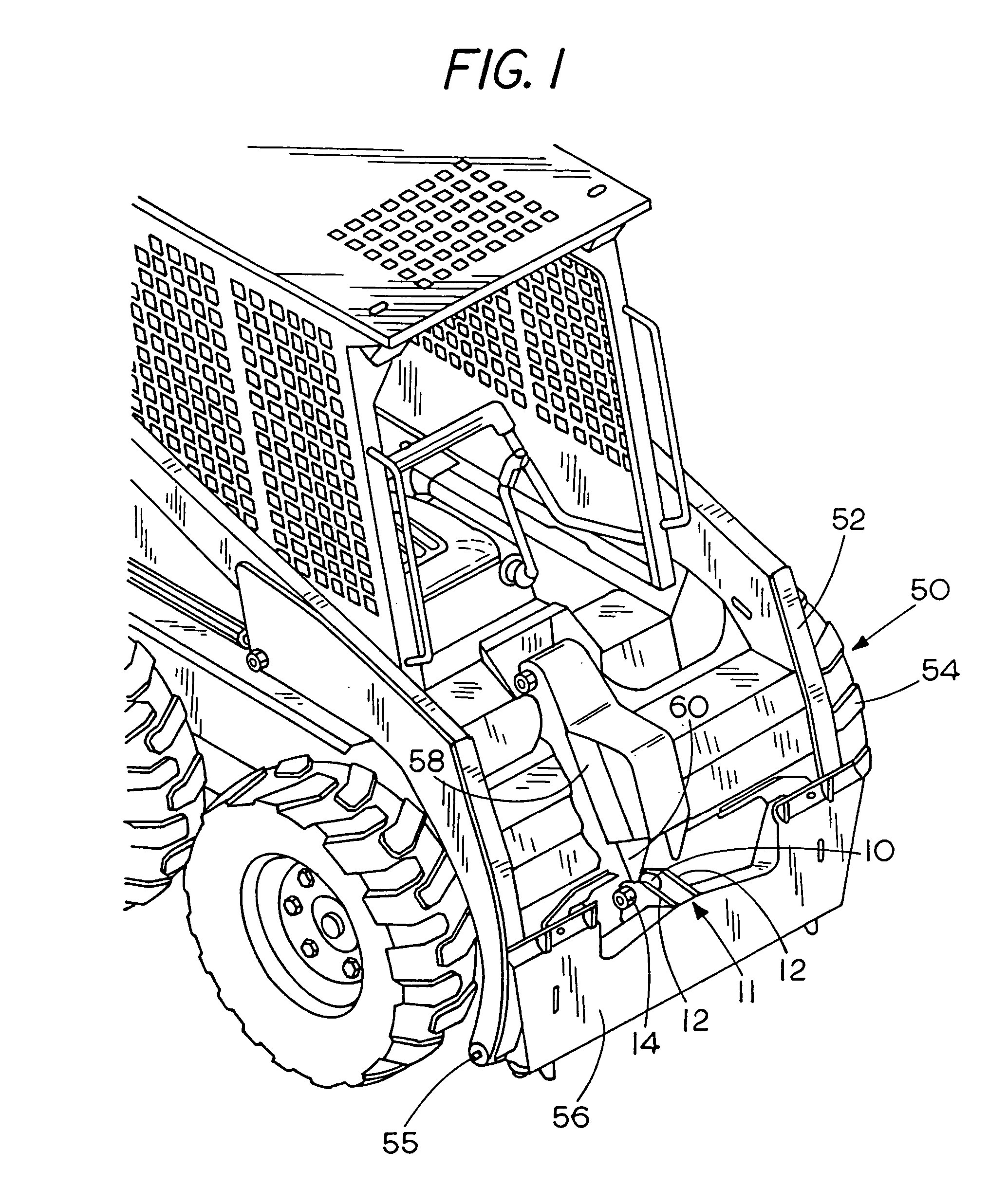
[0012]In FIG. 1, a skid steer loader 50 is shown as one example of an application of the invention. The loader 50 has lift arms 52 that are raised and lowered. As can be seen, the loader is supported on wheels 54 for movement along the ground. The lift arms 52 have forward ends 55 on which a quick attachment plate 56 is pivotally mounted. A hydraulic actuator shown at 58 has a rod 60, which includes a rod end 10 forming a first member at its outer end. The rod end 10 is used for tilting the plate 56 about the axis of pins 55, at the lower ends of the lift arms. The plate 56 is used for mounting a bucket or other attachments.

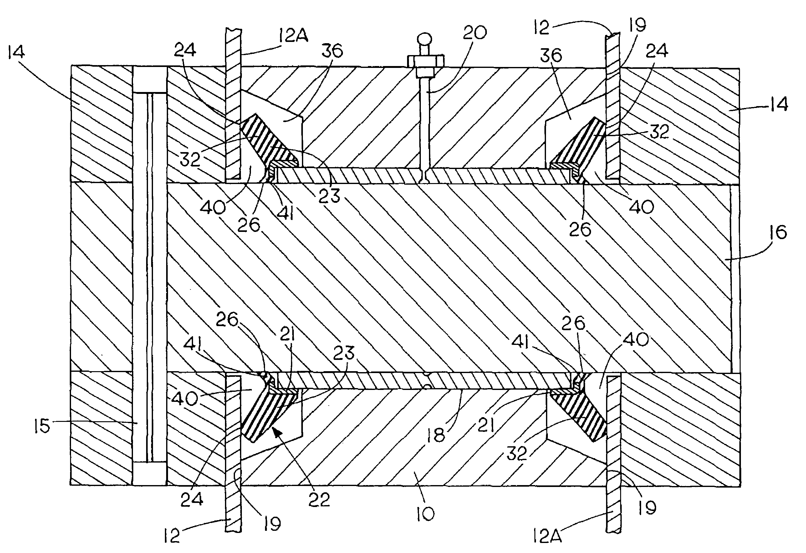
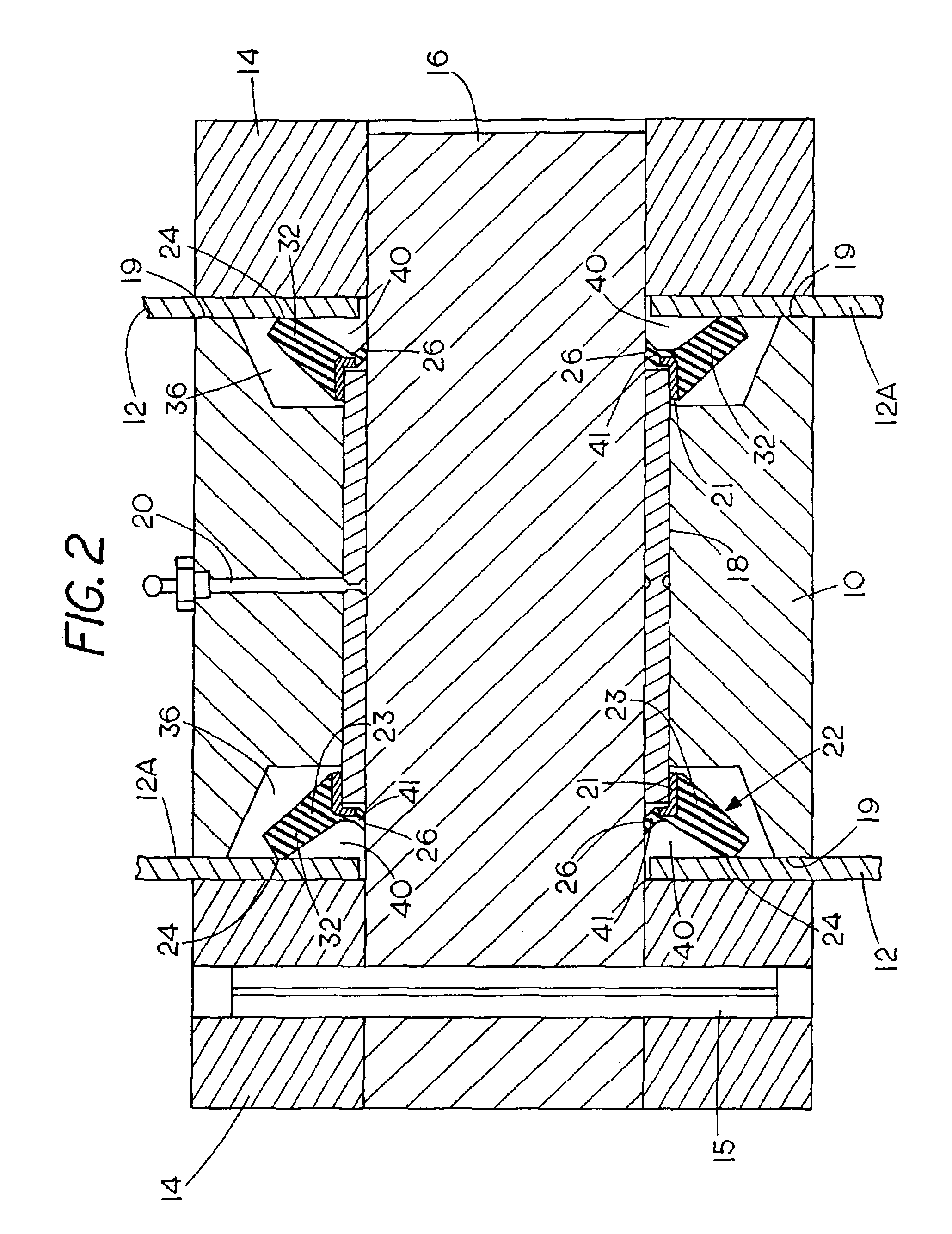
[0013]The tilting plate has a rod end attachment brackets 11 that is a second member formed with spaced side plates or ears 12, which are fixed to the tilting plate spaced apart sufficiently so the rod end interfits between plates 12, or in other words the bracket 11 receives the rod end. On the outer sides of these plates 12, there are tubular hubs 14 that have ...


PUM


Abstract

A pair of pivoting parts are held together with a pin, with a first part, such as a rod end of a hydraulic actuator, positioned between two flanges of a bracket, with the flanges having surfaces mating with sides surfaces of the rod end. A seal is placed in each of a pair of recesses on the opposite side surfaces of the rod end to provide an annular seal around the surface of the pin as the parts pivot, and also having a flange forming a side seal that seats on one of the mating surfaces of the bracket at a location spaced outwardly from the pin and extending annularly around the pin. The seal portion engaging the pin is spaced inwardly from the respective side surface of the bracket, and the outer annular lip seals a space surrounding the pin to form a pocket to receive grease that is used to lubricate the pin relative to the rod end.

Description

BACKGROUND OF THE INVENTION[0001]This invention relates to a seal for pins that connect two pivoting parts designed to keep dust away from a bushing for the pin, and to keep lubricating grease trapped for lubricating sliding side surfaces. In an exemplary application such as holding the rod end of a hydraulic cylinder to a bracket at the top of a loader bucket, the pin is generally held stationary, and the rod end will pivot on the pin as the bucket is tilted.[0002]Such connecting pins will operate in dusty conditions and it is important for the life of the bushing that is used on the rod end to keep grit and dirt out, and also to keep grease, used as a lubricant, in place.[0003]Excessive introduction of dirt in the pivoting parts causes wear and the need for replacement.[0004]A rod end of a hydraulic cylinder is generally positioned between two side hub members and connects to the hubs with a cylindrical pin. Dust and dirt can get in along the sides of the rod end, as well as along...

Claims


Application Information

Patent Timeline
Patent Type & Authority Patents(United States)
IPC IPC(8): F16C11/00
CPCF16J15/3236F16J15/3456Y10T403/52Y10T403/259F16C33/74F16C11/045F16C2350/26F16B2200/60
Inventor BROCK, KNUTE K.SHELBOURN, WILLIAM C.PURVIS, ROBERT E.O'BRIEN, TIMOTHY T.
Owner DOOSAN BOBCAT NORTH AMERICA INC
Why Eureka
Try Eureka