Modular jack

a module jack and jack technology, applied in the direction of coupling devices, two-part coupling devices, electrical apparatus, etc., can solve the problems of relatively high relatively complex assembling structure of modular jacks, and relatively high manufacturing cost of modular jacks, so as to achieve easy and secure assembly

Inactive Publication Date: 2008-05-13
HON HAI PRECISION IND CO LTD
View PDF8 Cites 3 Cited by
  • Summary
  • Abstract
  • Description
  • Claims
  • Application Information

AI Technical Summary

Benefits of technology

[0007]It is an object of the present invention to provide a simple modular jack which is capable of being easily and securely assembled to a printed circuit board.

Problems solved by technology

Apparently, the assembling structure of the modular jack is relatively complicate since the first shielding forms a leg and the circuit board must define a cutout.
As a result, the manufacture of the modular jack becomes relatively complex and the cost of the modular jack becomes relatively high.
Furthermore, the legs are too tiny to securely fix the modular jack on the circuit board.

Method used


Image

  • Modular jack
  • Modular jack
  • Modular jack

Examples


Embodiment Construction

[0016]Reference will now be made to the drawing figures to describe the present invention in detail.

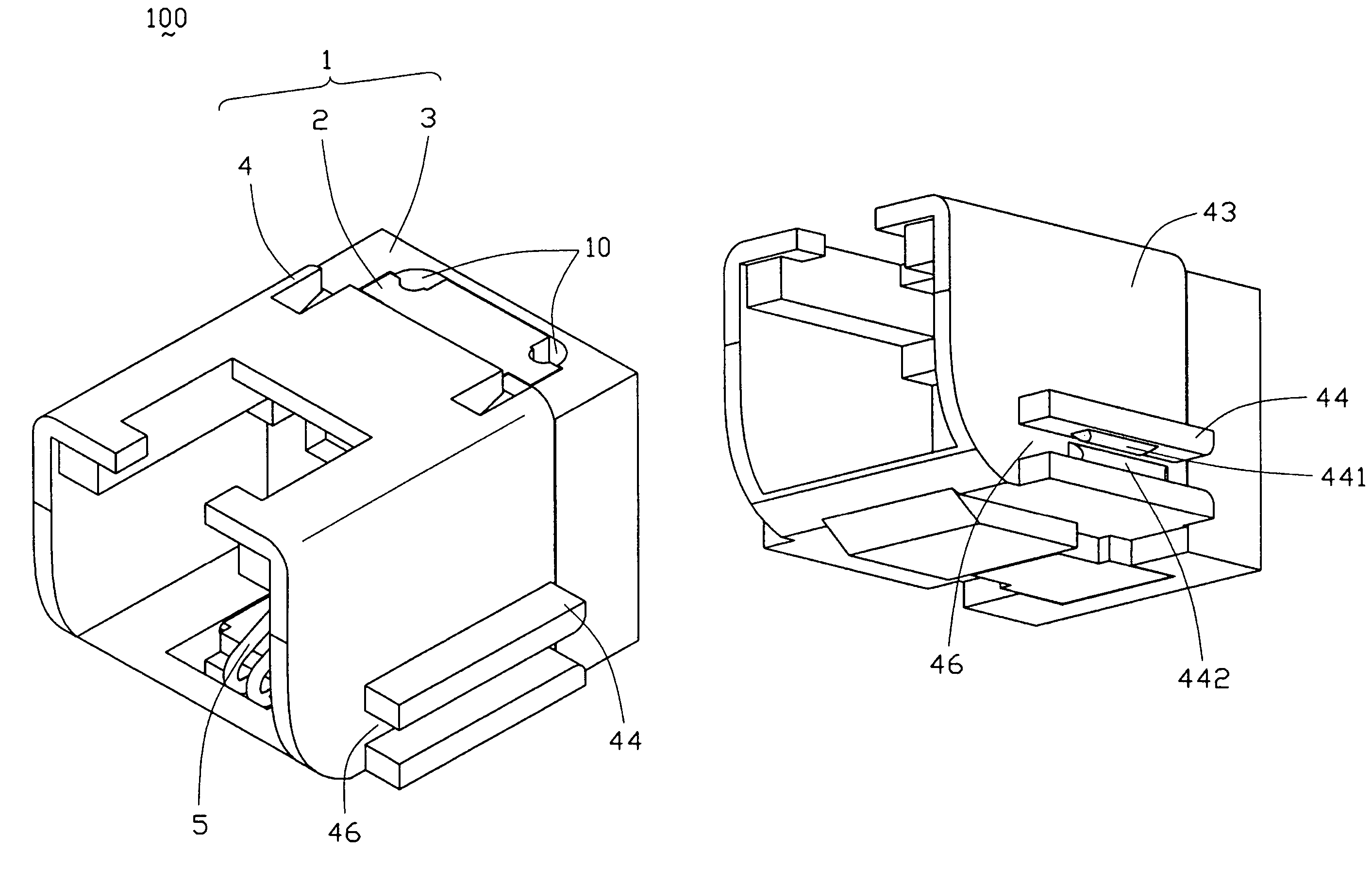
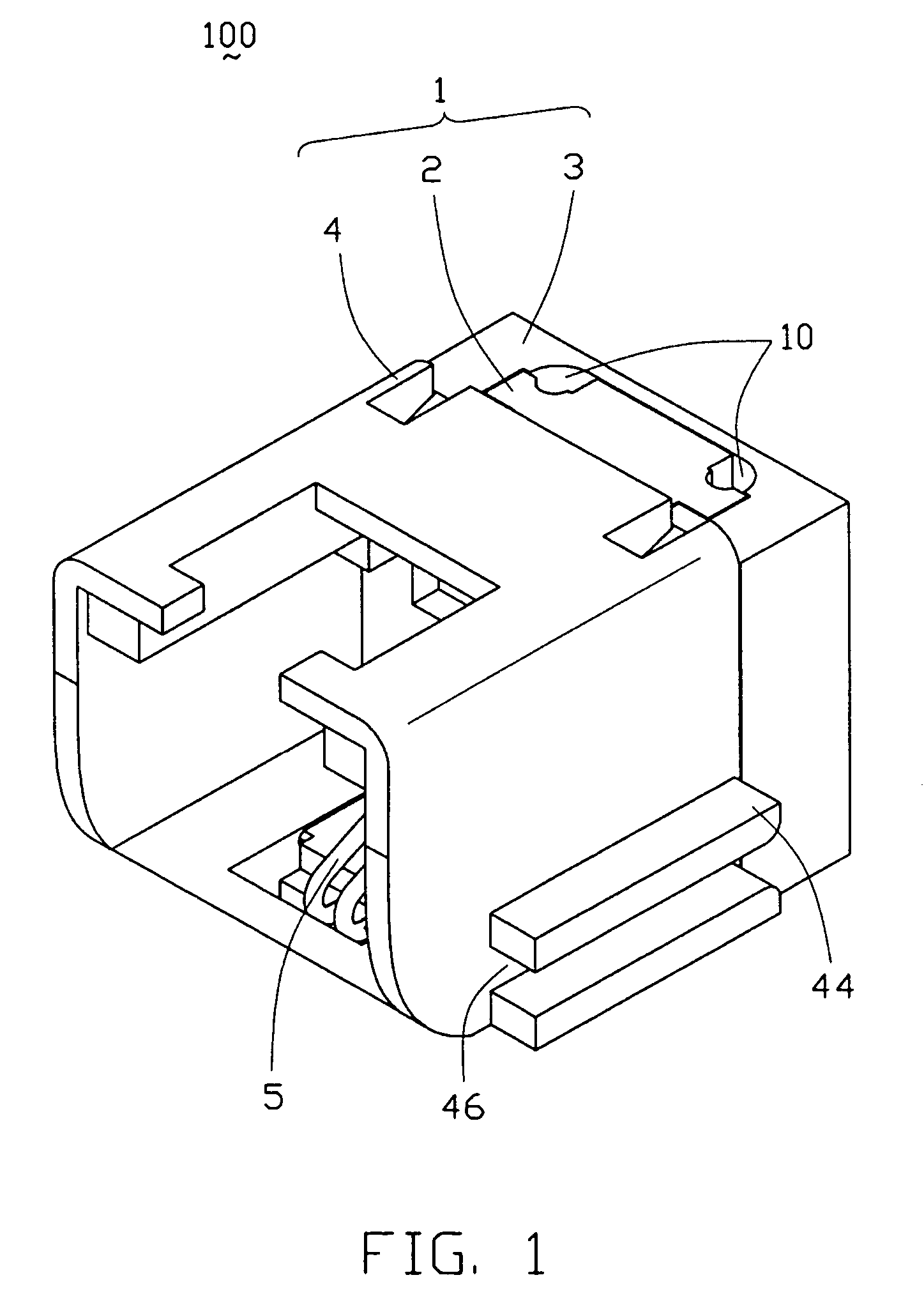
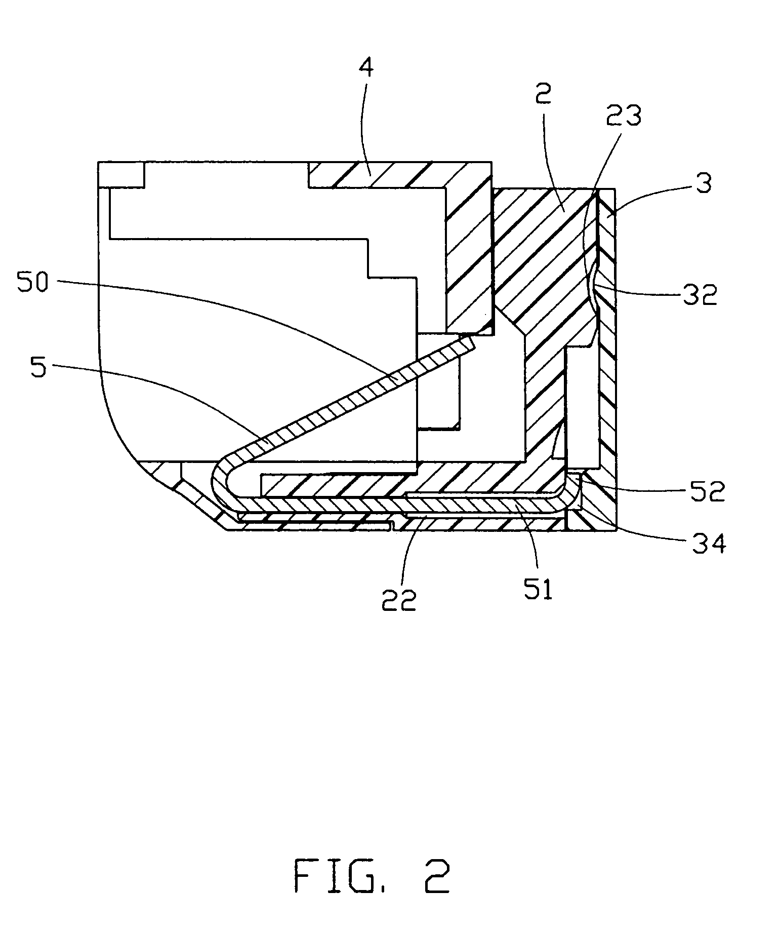
[0017]Referring to FIGS. 1-3, a modular jack 100 in accordance with a preferred embodiment of the present invention has a housing 1 including an insert module 2, a presser 3, and a main body 4, and a plurality of terminals 5 received in the insert module 2 of the housing 1.

[0018]The insert module 2 is substantially in a L-shaped configuration and has a plate section 25 and a base section 26. The base section 26 extends forwardly from a bottom edge of the plate section 25. The plate section 25 has a pair of guide sections 20 formed on lateral sides thereof and a pair of first cutouts 24 defined adjacent to corresponding guide sections 20 in a rear wall (not labeled) thereof. The pair of first cutouts 24 extends downwardly toward each other thereby forming a V-shaped configuration. The plate section 25 further defines an indentation 23 in the rear wall thereof. The base section 26 has a...


PUM


Abstract

A modular jack (100) is adapted for mounting on a printed circuit board (6) and has a housing (1) and a plurality of terminals (5) received in the housing. The housing includes a main body (4), an insert module (2), and a presser (3). The main body defines a cavity (40), a pair of grooves (41), and a pair of slots (42). The main body includes a pair of side walls (43). A pair of engaging ribs (44) outwardly project from each side wall and parallel to each other, thereby forming a mounting channel (46) for engaging the printed circuit board between the engaging ribs. As a result, the modular jack is mounted on the printed circuit board. The insert module has a pair of lead sections (21) slidably received in the grooves and a pair of guide sections (20). The presser has a pair of channels (30) slidably receiving the guide sections of the insert module and a pair of latches (33) reliably engaging with the slots of the main body. The presser further has a pair of blocks (31) abutting against bottom edges of the guide sections.

Description

BACKGROUND OF THE INVENTION[0001]1. Field of the Invention[0002]The present invention generally relates to an electrical connector, and more particularly to a modular jack with a simple structure and a simplified method for mounting the modular jack on a printed circuit board.[0003]2. Description of the Prior Art[0004]Modular jacks are widely used in telecommunication systems for facilitating connection of components thereof. As electrical devices become thinner, electrical connectors should become smaller to benefit such thin and compact electrical devices.[0005]U.S. Pat. No. 6,095,865 discloses a related modular jack. The conventional modular jack includes an insulative housing, a terminal assembly and a shielding assembly. A pair of legs outwardly and downwardly extends from opposite sides of the shield. A circuit board defines a rectangular cutout for snugly accommodating the modular jack and a pair of mounting slits for engaging with the legs, thereby securely mounting the modu...

Claims


Application Information

Patent Timeline
Patent Type & Authority Patents(United States)
IPC IPC(8): H01R24/00H01R13/648
CPCH01R24/64H01R13/502
Inventor WANG, WEI CHE
Owner HON HAI PRECISION IND CO LTD
Why Eureka
Try Eureka