Heat dissipation assembly

a technology of heat dissipation assembly and assembly body, which is applied in the direction of insulated conductors, power cables, semiconductor/solid-state device details, etc., can solve the problems of abnormal operation or damage, large heat generation of modem electronic components such as central processing units of computers, and unfavorable use of the modem. , to achieve the effect of convenient and secure assembly

Inactive Publication Date: 2006-09-19
HON HAI PRECISION IND CO LTD
View PDF14 Cites 9 Cited by
  • Summary
  • Abstract
  • Description
  • Claims
  • Application Information

AI Technical Summary

Benefits of technology

[0007]Accordingly, an object of the present invention is to provide a heat dissipation assembly which can be easily and securely assembled.
[0008]In order to achieve the object set out above, a heat dissipation assembly in accordance with a preferred embodiment of the present invention comprises a printed circuit board, an electronic component mounted on the printed circuit board, a heat dissipation device mounted on the electronic component, four securing members secured to the heat dissipation device and four positioning members extend through the printed circuit board. The positioning members are covered over by four resilient members disposed in the securing members. The positioning members pull the securing members toward the printed circuit board. In the present invention, the positioning members relatively position the heat dissipation device parallel to the electronic component, so that displacement parallel to the electronic component is avoided for the heat dissipation device. The positioning members pull the securing members toward the printed circuit board so that the heat dissipation device can be intimately attached to the electronic component. The resilient members prevent the electronic component from being damaged during shock or vibration.

Problems solved by technology

Numerous modem electronic components such as central processing units (CPUs) of computers generate large amounts of heat during operation.
The heat must be efficiently removed from the CPU; otherwise, abnormal operation or damage may result.
However, attachment and detachment of the screws are unduly laborious.
Furthermore, the PCB is prone to be deformed due to overloaded force on partial portions thereof.
Unfortunately, tools are required to have the engaging portions engaged with the socket or the retention module.
Engagement and disengagement of the clip from the socket or the retention module are still unduly laborious.
Furthermore, the heat dissipation device is prone to displace relative to the CPU.
This adversely affects the heat conduct capability from the CPU to the heat dissipation device.

Method used


Image

  • Heat dissipation assembly
  • Heat dissipation assembly
  • Heat dissipation assembly

Examples


Embodiment Construction

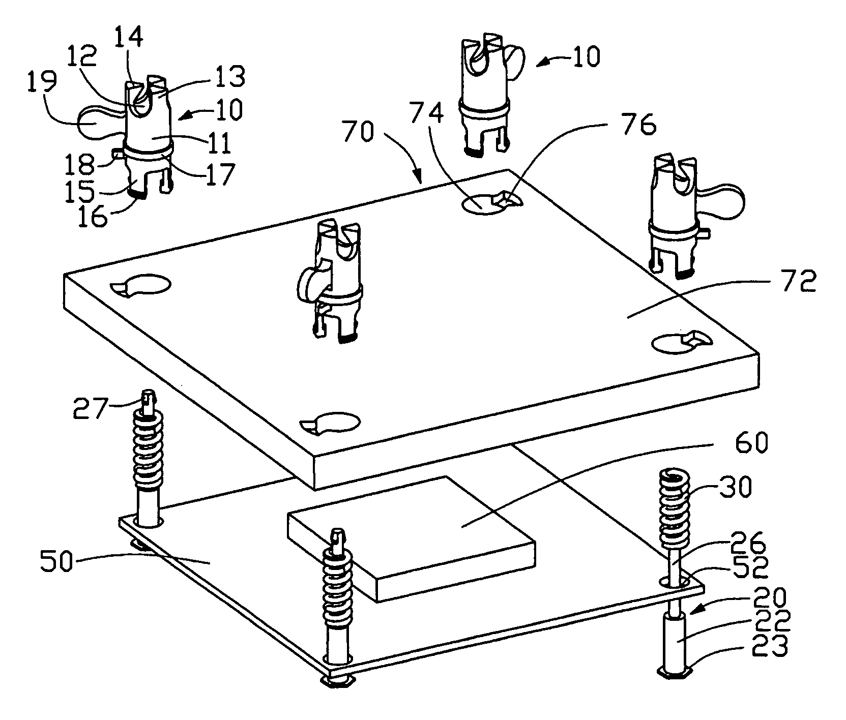
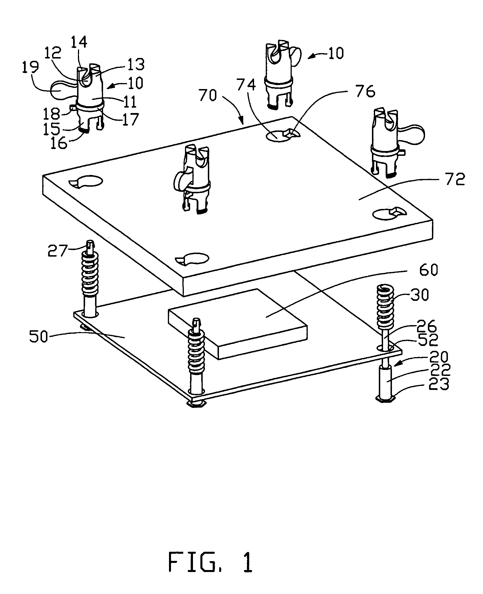
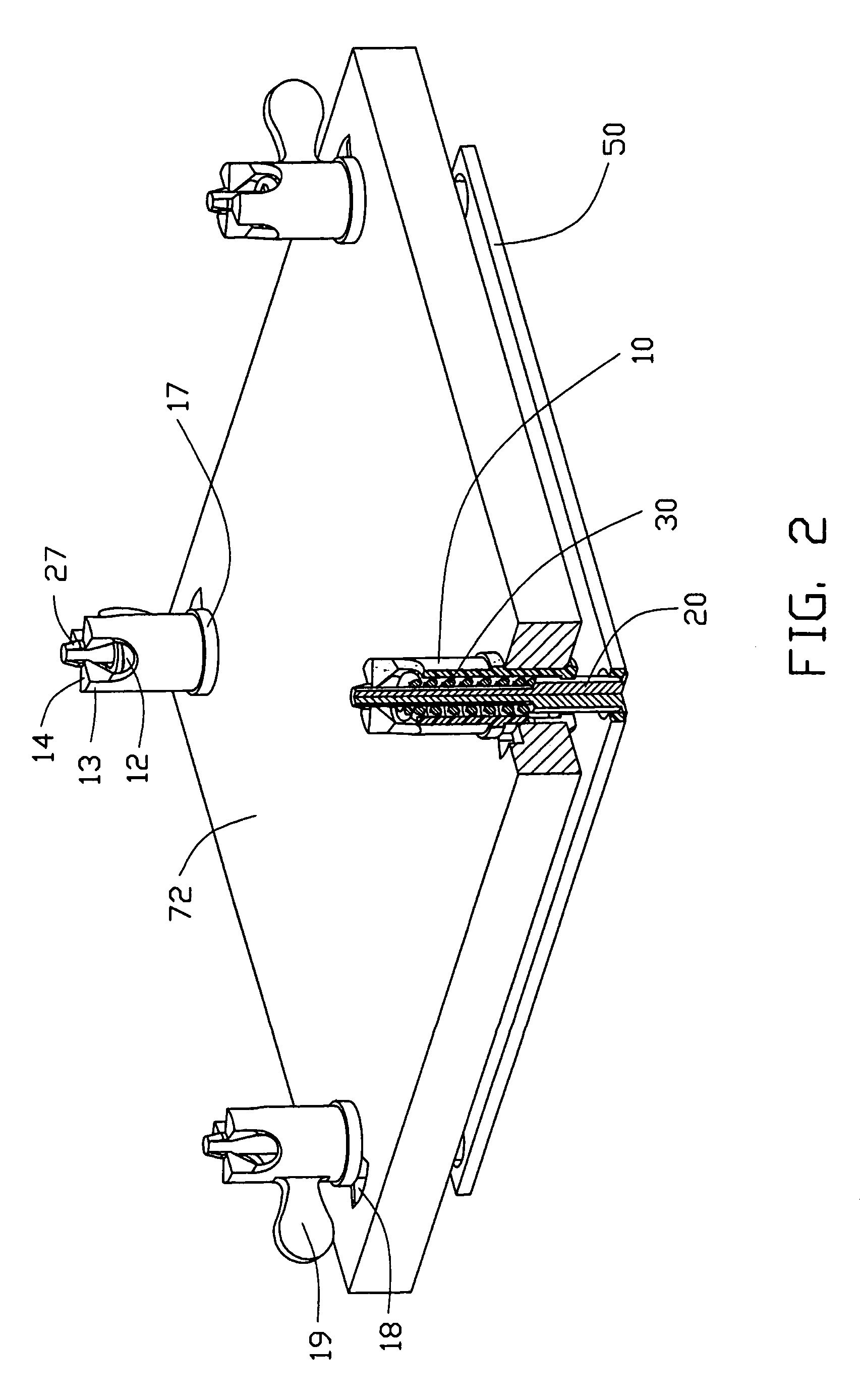
[0012]Referring to FIGS. 1–2, a heat dissipation assembly in accordance with the preferred embodiment of the present invention comprises a fastening apparatus, a PCB 50, an electronic component 60 mounted on the PCB 50 and a heat dissipation device 70 mounted on the electronic component 60 for removing heat therefrom.

[0013]The PCB 50 defines four through holes 52 therein spaced from and symmetrically around the electronic component 60. The heat dissipation device 70 has a planar base 72 defining four openings 74 therein corresponding to the through holes 52 of the PCB 50, and four dents 76 in communication with corresponding openings 74. Each dent 76 has a substantially 60 degrees sector transverse section.

[0014]The fastening apparatus comprises four securing members 10, four positioning members 20 and four resilient members 30. Each securing member 10 comprises a cylindraceous body 11 within which an axial hole 12 is defined. Three paws 13 extend from an end of the body 11 along an...


PUM


Abstract

A heat dissipation assembly of the present invention includes a printed circuit board (50), an electronic component (60) mounted on the printed circuit board, a heat dissipation device (70) mounted on the electronic component, four securing members (10) secured to the heat dissipation device and four positioning members (20) extend through the printed circuit board. The positioning members are covered over by four resilient members (30) disposed in the securing members. The positioning members pull the securing members toward the printed circuit board.

Description

BACKGROUND OF THE INVENTION[0001]1. Field of the Invention[0002]The present invention relates to heat dissipation assemblies, and more particularly to a heat dissipation assembly removing heat from an electronic component.[0003]2. Description of Prior Art[0004]Numerous modem electronic components such as central processing units (CPUs) of computers generate large amounts of heat during operation. The heat must be efficiently removed from the CPU; otherwise, abnormal operation or damage may result. Typically, a heat dissipation device is mounted on the CPU to remove heat therefrom.[0005]Mostly, holes are defined in printed circuit boards (PCBs). Screws are inserted through the heat dissipation device and engaged within the holes of the PCB to mount the heat dissipation device to the CPU. However, attachment and detachment of the screws are unduly laborious. Furthermore, the PCB is prone to be deformed due to overloaded force on partial portions thereof.[0006]For overcoming the above-...

Claims


Application Information

Patent Timeline
Patent Type & Authority Patents(United States)
IPC IPC(8): H05K7/20G06F1/16H01L23/40
CPCH01L23/4093H01L2924/0002H01L2924/00
Inventor LEE, HSIEH KUNLAI, CHENG-TIENZHOU, SHI-WEN
Owner HON HAI PRECISION IND CO LTD
Why Eureka
Try Eureka