Magnetic propulsion motor

a technology of magneto-propulsion motor and magneto-electric brake, which is applied in the direction of dynamo-electric brake control, dynamo-electric machines, control systems, etc., can solve the problems of ineffective magnetic propulsion, current motors that do not take into account the shape, and current motors that do not effectively diminish or eliminate magnetic locks. , to achieve the effect of reducing the repelling for

Inactive Publication Date: 2008-06-10
FUTURE FORCE LLC
View PDF6 Cites 22 Cited by
  • Summary
  • Abstract
  • Description
  • Claims
  • Application Information

AI Technical Summary

Benefits of technology

[0006]The present invention relates to a magnetic propulsion motor comprising a magnetic drive assembly comprising a drive magnet, a rotating hub, and a motion magnet attached to the rotating hub to rotate the motion magnet proximate to the magnetic drive assembly. A driving force is applied to the magnetic drive assembly, which causes the drive magnet to rotate to a position proximal to the motion magnet when the motion magnet is in a position proximate to the magnetic drive assembly. This arrangement exerts a repelling force on the motion magnet from the drive magnet as the motion magnet rotates away from the magnetic drive assembly. The rotation of the drive magnet also rotates the drive magnet to a position distal to the motion magnet as the motion magnet approaches the position proximate to the magnet drive assembly thereby minimizes the repelling force exerted on the motion magnet from the drive magnet as the motion magnet rotates towards the magnetic drive assembly.

Problems solved by technology

Magnetic propulsion has traditionally not worked effectively in the past due to magnetic lock.
Current magnetic propulsion motors have not been effective in diminishing or eliminating magnetic lock.
Additionally, current motors do not take into consideration the shape of the motion magnets or the effect, in certain configurations, that magnetic shielding can have.
Thus, current motors are generally inefficient.

Method used


Image

  • Magnetic propulsion motor
  • Magnetic propulsion motor
  • Magnetic propulsion motor

Examples


Embodiment Construction

[0021]The present invention relates to a magnetic propulsion motor. More specifically, the present invention relates to a system and method of generating power by using magnets and magnetic fields. An output of power is obtained from rotating motion magnets through one or more magnetic acceleration fields created by push magnets.

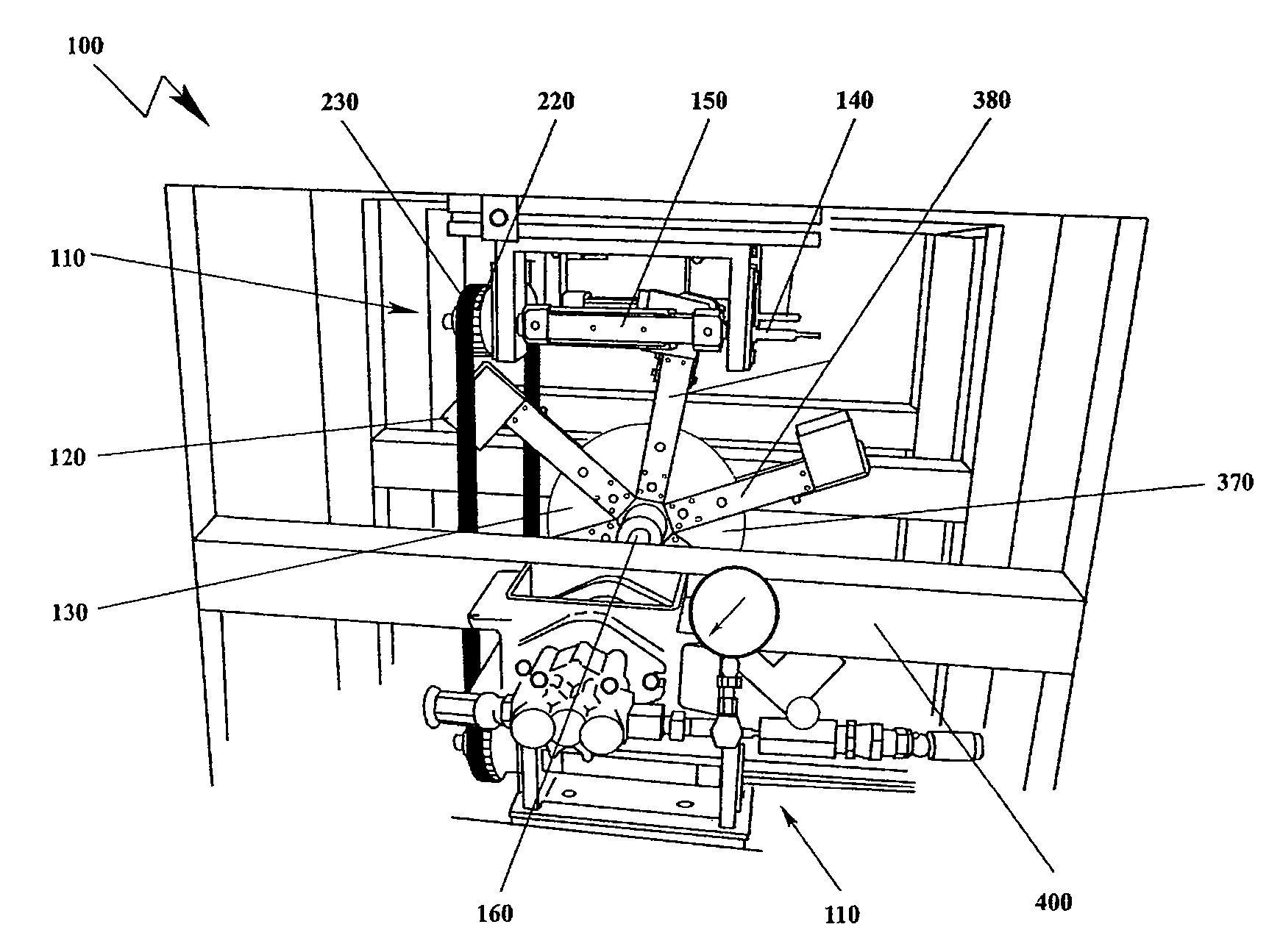
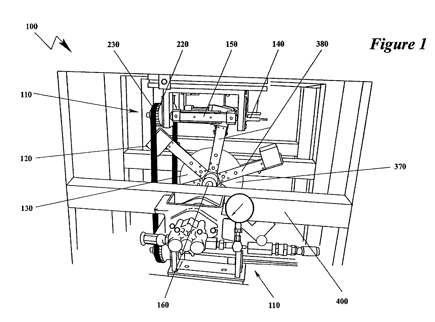
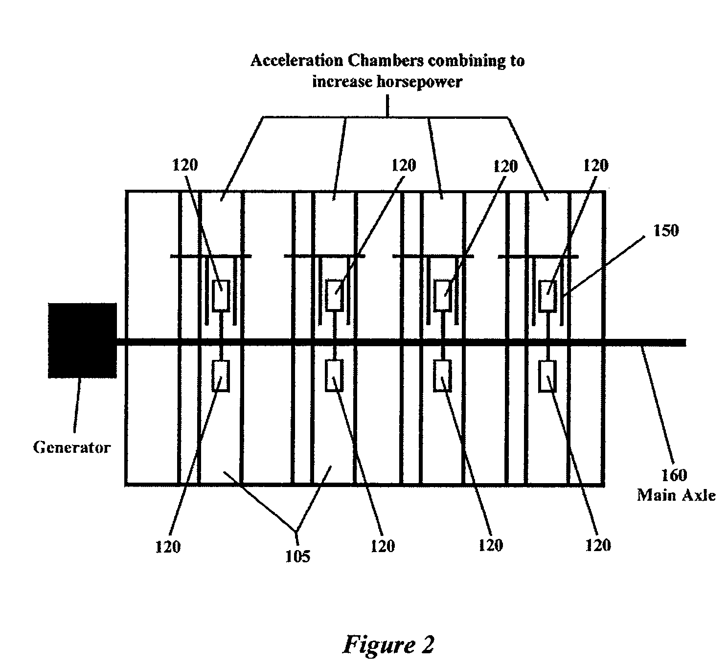
[0022]According to one embodiment of the present invention shown in FIG. 1, a magnetic propulsion motor 100 comprises at least one acceleration chamber 105 (shown in FIG. 2) within main frame 400. Each acceleration chamber 105 includes at least one acceleration field generator 110 and at least one motion magnet 120 and a rotating hub 130 coupled thereto. As described in more detail below and shown in FIG. 9, the rotating hub 130 generally comprises a base 370 and an extension arm 380 for each motion magnet 120. The extension arm 380 secures the motion magnet 120 to the base 370.

[0023]The rotation of the rotating hub 130 causes each motion magnet 120 to pass ...


PUM


Abstract

The present invention relates to a magnetic propulsion motor comprising a magnetic drive assembly comprising a drive magnet, a rotating hub, and a motion magnet attached to the rotating hub to rotate the motion magnet proximate to the magnetic drive assembly. A driving force is applied to the magnetic drive assembly, which causes the drive magnet to rotate to a position proximal to the motion magnet when the motion magnet is in a position proximate to the magnetic drive assembly. This arrangement exerts a repelling force on the motion magnet from the drive magnet as the motion magnet rotates away from the magnetic drive assembly. The rotation of the drive magnet also rotates the drive magnet to a position distal to the motion magnet as the motion magnet approaches the position proximate to the magnet drive assembly thereby minimizes the repelling force exerted on the motion magnet from the drive magnet as the motion magnet rotates towards the magnetic drive assembly.

Description

CROSS-REFERENCE TO RELATED APPLICATION(S)[0001]This application is a continuation of International application number PCT / US2005 / 023704, filed Jun. 30, 2005, which claims priority to U.S. provisional patent application Ser. No. 60 / 584,298, filed Jun. 30, 2004, the contents of both are incorporated herein by reference in their entirety.FIELD OF THE INVENTION[0002]The present invention relates to a magnetic propulsion motor. In particular, the present invention relates to a motor, wherein power is generated using magnets and magnetic fields. Magnets are accelerated through the magnetic fields creating a rotational movement about an axis.BACKGROUND OF THE INVENTION[0003]Magnetic propulsion has traditionally not worked effectively in the past due to magnetic lock. That is, it takes as much energy to enter into a magnetic field as is generated leaving the field. However, if push or “drive” magnets are taken out of position to affect the conflicting magnetic field created by the motion ma...

Claims


Application Information

Patent Timeline
Patent Type & Authority Patents(United States)
IPC IPC(8): H02K7/06
CPCH02K49/102H02K53/00
Inventor TKADLEC, MIKE
Owner FUTURE FORCE LLC
Why Eureka
Try Eureka