Dual motor upright vacuum cleaner

a vacuum cleaner and upright technology, applied in the field of upright vacuum cleaners, to achieve the effect of reducing suction pressur

Active Publication Date: 2008-06-17
TACONY A MISSOURI
View PDF11 Cites 63 Cited by
  • Summary
  • Abstract
  • Description
  • Claims
  • Application Information

AI Technical Summary

Problems solved by technology

However, some of these prior art vacuum cleaners turn one motor and fan unit off when the other is on since they are used for different purposes.

Method used


Image

  • Dual motor upright vacuum cleaner
  • Dual motor upright vacuum cleaner
  • Dual motor upright vacuum cleaner

Examples


Embodiment Construction

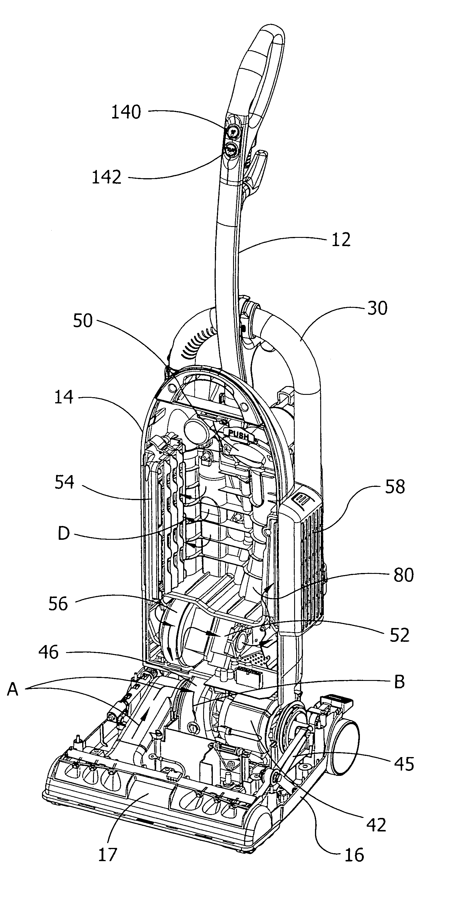
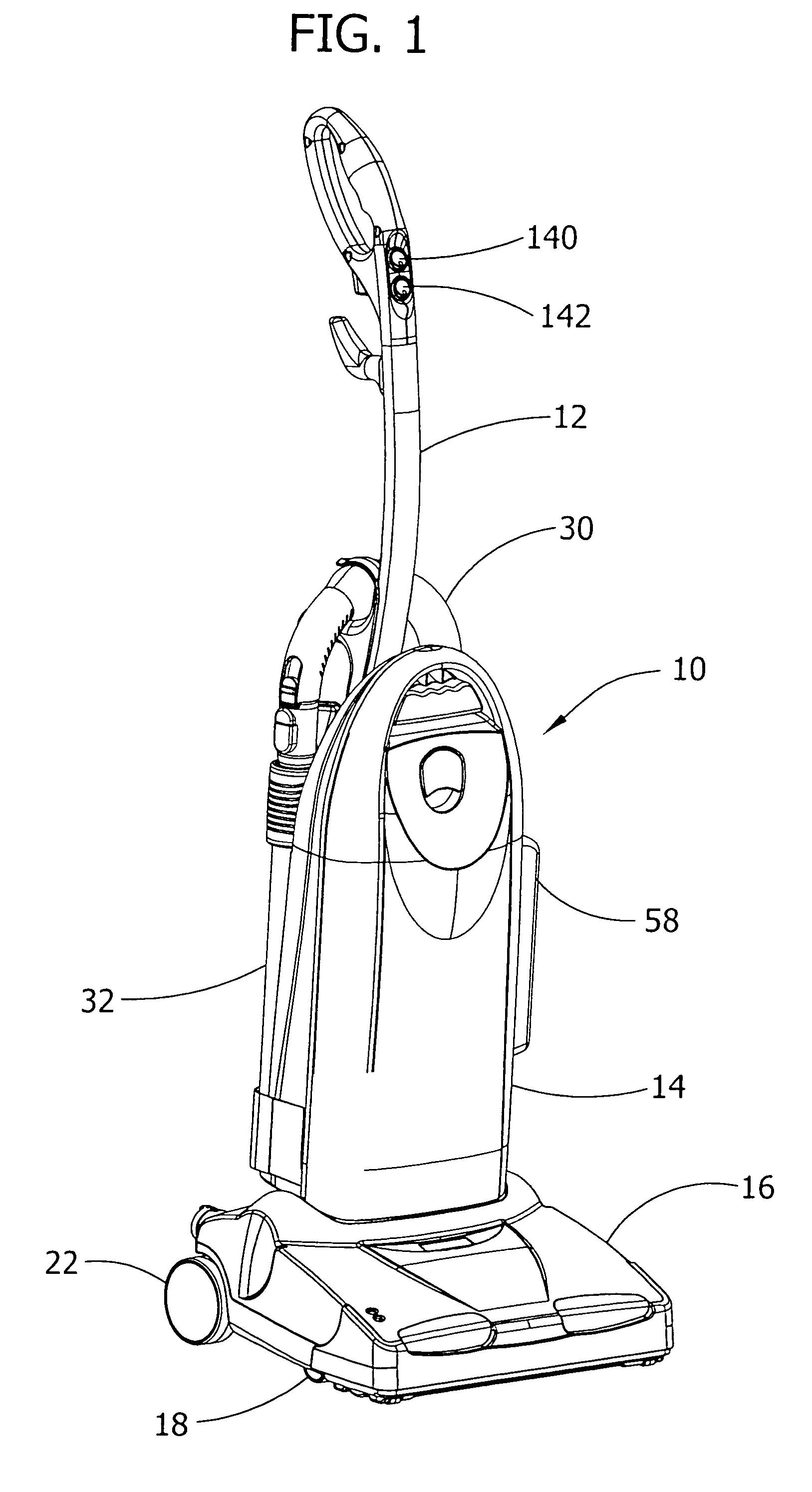
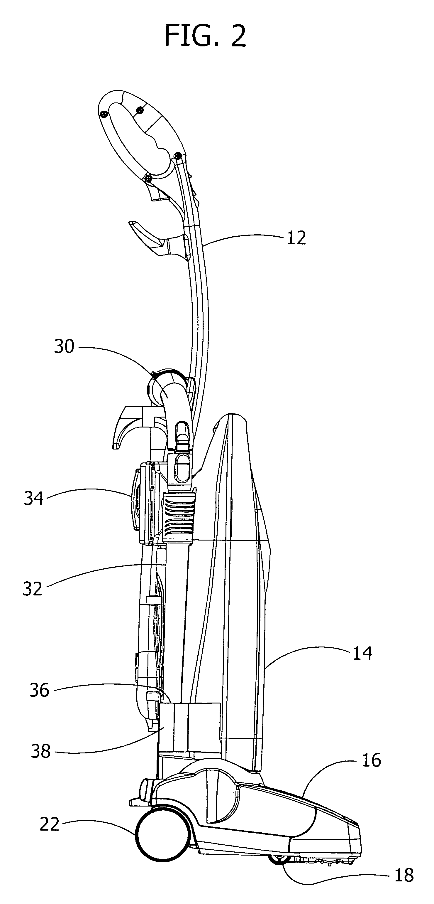
[0025]Referring to FIG. 1, an upright vacuum cleaner 10, constituting a preferred embodiment of the present invention, is shown having a handle 12 extending out of and connected to an upright housing 14. The housing 14 is pivotally connect to a cleaning head 16 so that the handle 12 can be pivoted between a generally horizontal position to a generally vertical position, as is generally well known in the art, in order to maneuver the cleaning head 16 over a surface to be cleaned. The vacuum cleaner 10 is supported by a pair of front wheels 18 and 20 (see FIGS. 2, 3 and 4) and a pair of back wheels 22 and 24.

[0026]A partially flexible cleaning hose 30 is attached to the back of the housing 14 and carries a nozzle 32 (see FIG. 5) for above-floor cleaning. Removably carried on the back of housing 14 are above-floor cleaning attachments 34 which are adapted to be fitted to the end 36 of nozzle 32 for cleaning various above-floor surface configurations and materials in a well known manner...


PUM


Abstract

An upright vacuum cleaner having dual cleaning motor and fan units is provided having a cleaning head engagable with a floor and a suction nozzle and a brush roller rotatably mounted therein. A first motor and fan unit is mounted in the vacuum cleaner for producing suction in the suction nozzle and is operatively connected to the brush roller for rotating it. An upright housing is connected to the cleaning head, the housing having a handle for moving the vacuum cleaner along the floor during floor cleaning use. Contained in the housing are a dirt storage container, a passageway leading from the suction nozzle in the cleaning head to the storage container and a second motor and fan unit operatively associated with the storage container for drawing dirt laden air from the cleaning head through the passageway and into the storage container simultaneously with operation of the first motor and fan unit.

Description

BACKGROUND OF THE INVENTION[0001]The present invention relates to upright vacuum cleaners and, more particularly, to an upright vacuum cleaner having a floor cleaning nozzle and an above-floor cleaning nozzle and two motor and fan units as vacuum sources.[0002]Upright vacuum cleaners that utilize two motor and fan units for providing sources of suction are known where one motor and fan unit draws air through the walls of a dirt collection bag, or the like, commonly called a clean air motor, and a second motor and fan unit is disposed in the cleaning head of the vacuum cleaner through which dirt laden air passes, commonly called a dirty air motor. However, some of these prior art vacuum cleaners turn one motor and fan unit off when the other is on since they are used for different purposes. Typically, the clean air motor and fan unit is used for off the floor cleaning with accessories for cleaning furniture and draperies and the like, whereas the dirty air motor and fan unit is used ...

Claims


Application Information

Patent Timeline
Patent Type & Authority Patents(United States)
IPC IPC(8): A47L5/30A47L5/32A47L9/22
CPCA47L5/30A47L5/32A47L9/22
Inventor BLOCKER, DOUGLAS L.KAIDO, JOHN F.
Owner TACONY A MISSOURI
Why Eureka
Try Eureka