Rapidly deployable temporary modular structures and component elements thereof

a temporary modular structure and rapid deployment technology, applied in the direction of girders, threaded fasteners, mechanical devices, etc., can solve the problems of limited strength, excessive flexibility, and unsatisfactory results

Active Publication Date: 2008-06-24
HAWES RAYMOND W
View PDF15 Cites 60 Cited by
  • Summary
  • Abstract
  • Description
  • Claims
  • Application Information

AI Technical Summary

Benefits of technology

[0012]Also according to the present invention, each T-slot structure is defined by two parallel slot side walls extending outwardly in parallel from an exterior main surface of a chord and by two slot face walls extending inwardly from the outer edges of the slot side walls and parallel to the exterior main surface. In addition, at least one inner surface of each T-slot is a bearing surface to support compressive forces resulting from tensional and torsional forces imposed through a T-bolt and wherein each plane defined by an innermost face of each cross slot is offset inwardly with respect to a corresponding exterior main wall surface of the chord, thereby forming an increased and diagonal main wall thickness between planes defined by the interior surfaces of each cross slot and a corresponding exterior main surface of the chord.

Problems solved by technology

Temporary structures of this nature have been and are presently built in a number of ways, all of which have proven unsatisfactory for one or more reasons.
While the wooden structures and in particular the bamboo structures are relatively light in relationship to their weight and are comprised of relatively strong individual components, that is, 2×4s and bamboo stalks, their strength is limited by the inherent properties of the materials and they tend to be excessively flexible because a required relatively large number of joints are necessary due to limitations on the available lengths of the materials.
Also, the joints and connections in such structures, which are typically fastened rope, twine, cord or nails, tend to be weak and excessively flexible and, as a result, tend to rotate about the joints.
Such measures as are typically taken to make the joints in such structures stronger and more rigid, however, such as bolts or clenched nails, rapidly increase the cost and construction time of the structures, as well as the time required to disassemble the structures.
Another disadvantage is that though the materials tend to be cheap and readily available the component elements are generally not readily reusable in subsequent structures, typically having been cut to specific sizes or damaged in use, thereby further increasing the costs of the structures.
While this type of structure is generally stronger and more rigid in both the elements and joints, and while the elements are typically reusable, the cost of the structure will be significantly greater.
Also, the elements and resulting structures will be significantly heavier and will be correspondingly more difficult, complex and time consuming to transport, assemble and disassemble, and will often require a wide variety of different component elements as the individual elements are not readily modifiable to specific needs.
The requirements of a satisfactory system for temporary structures comprised of modular common components that are capable of rapid deployment and of subsequent rapid modification and disassembly and removal and that are capable of meeting a wide range of purposes are straightforward but are difficult to satisfy.

Method used


Image

  • Rapidly deployable temporary modular structures and component elements thereof
  • Rapidly deployable temporary modular structures and component elements thereof
  • Rapidly deployable temporary modular structures and component elements thereof

Examples


Embodiment Construction

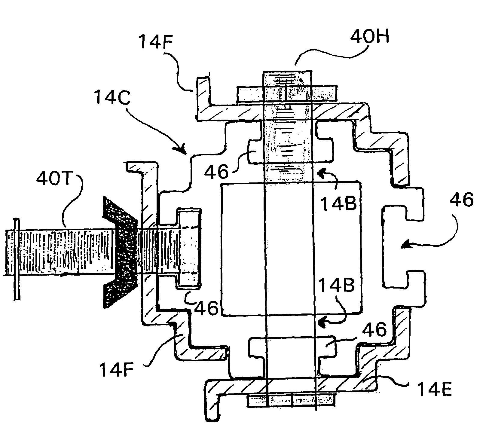
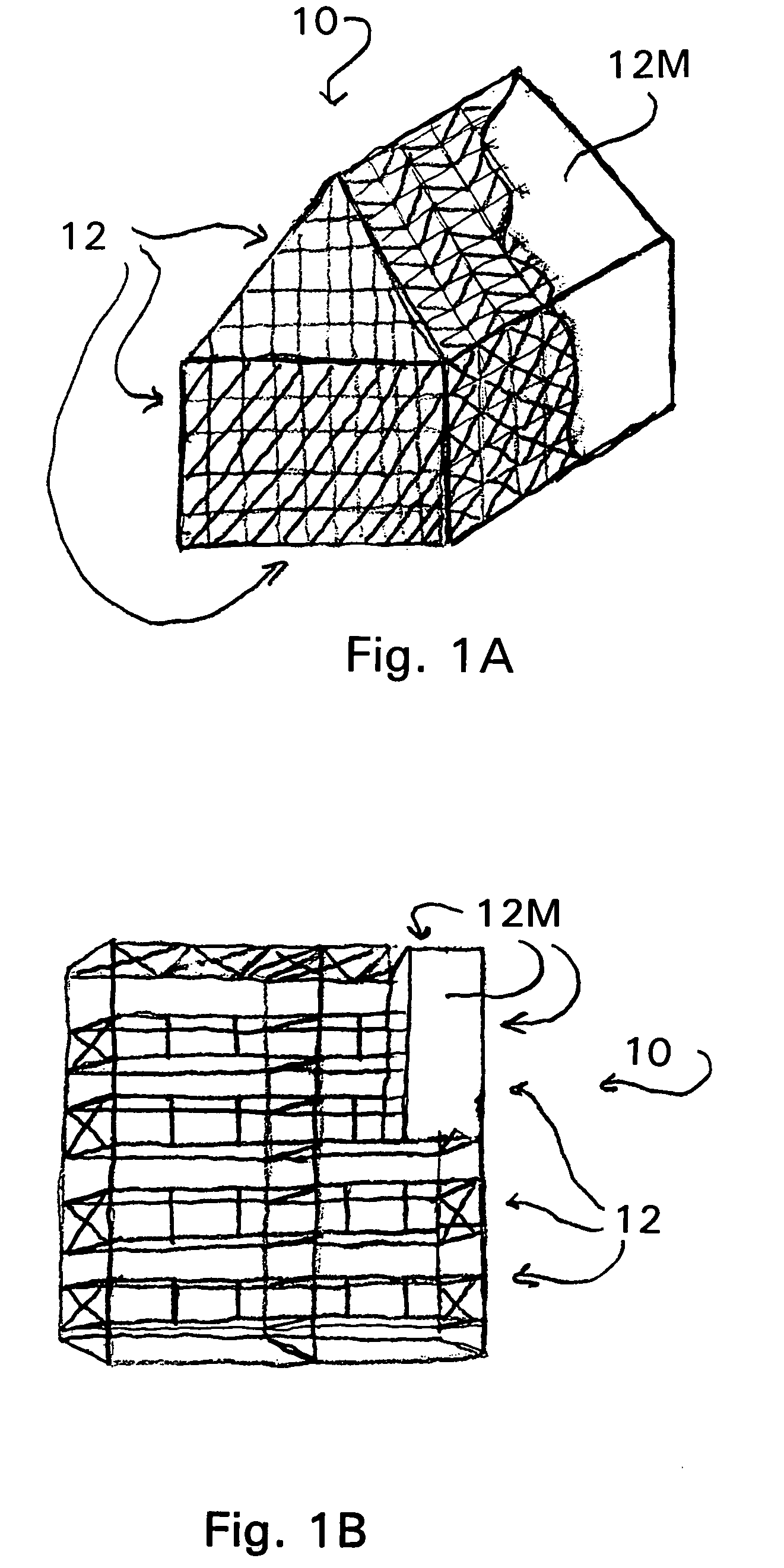
[0041]As described herein above, the present invention is directed to a method and apparatus for a system of modular common components for constructing temporary structures that are capable of rapid deployment or construction for a wide range of purposes and that are capable of subsequent rapid modification, disassembly or removal. For example, typical examples of such structures may include scaffolding structures, protective or containment enclosures with work spaces and accesses that enclose, for example, a storage tank or building, and protective or containment enclosure with work spaces and access supported by the structure it is enclosing, such as a bridge. Illustrative examples of such Structures 10, including Enclosures 10A and Scaffolding 10B, are shown in FIGS. 1A and 1B. It will be appreciated, however, that such structures represent only a limited part of the range of various types of structures that may be constructed according to the present invention.

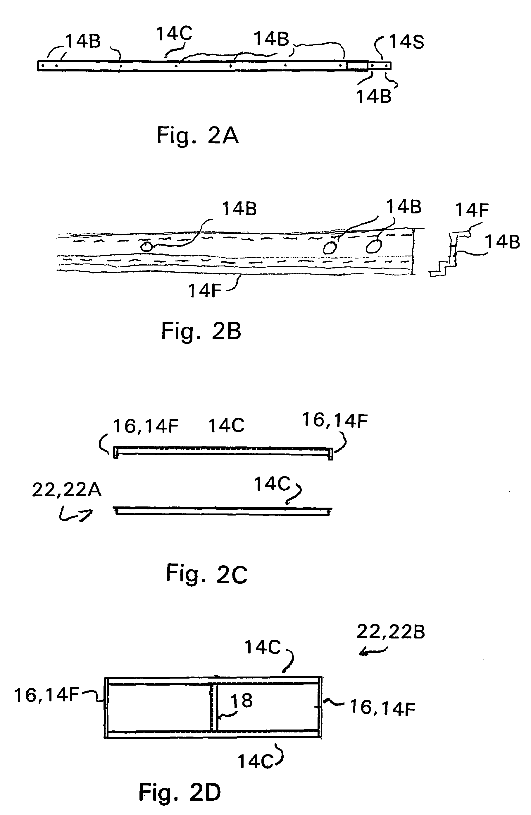
[0042]FIGS. 2A-2Y,...


PUM


Abstract

Modular structural components and structural connections including chords and forming strips. Each chord has a generally elongated square main body of four main walls surrounding a central bore and having a T-slot structure adapted to accept a bolt type fastener extending along each exterior main surface. Each forming strip is an elongated plate formed into strip segments oriented at right angles to each other and forming a W-shaped corner region, a face region with a bolt hole and an attachment region, each region forming a mating bearing surface with a surface of a chord.

Description

FIELD OF THE INVENTION[0001]The present invention relates to a method and apparatus for a system of modular common components for constructing temporary structures capable of rapid deployment or construction for a wide range of purposes and that are capable of subsequent rapid modification, disassembly or removal.BACKGROUND OF THE INVENTION[0002]Temporary structures are commonly used in a wide range of industries and for a wide range of purposes. Typical uses of such temporary structures include, for example, providing access and work spaces for work on such structures as buildings, bridges, large storage tanks, dams, large machines, such as trains or ships, and so on, and the work may range from construction, modification or refurbishing of all or part of such structures to the demolishing of such structures. Uses of such temporary structures may further include, for example, the providing and support of an enclosure to protect the structure being worked upon from the environment, ...

Claims


Application Information

Patent Timeline
Patent Type & Authority Patents(United States)
IPC IPC(8): E04B5/10E04C3/02E04C3/30E04H12/00E04C3/00E04G21/24E04G21/28E04G21/30F16B37/04
CPCE04C3/005E04G21/24E04G21/28E04G21/30F16B37/045E04G21/242
Inventor HAWES, RAYMOND W.
Owner HAWES RAYMOND W
Why Eureka
Try Eureka