Coupling for a clamp

a clamping and coupling technology, applied in the field of clamps, can solve the problem of limited clamping capability of each individual bar clamping devi

Inactive Publication Date: 2008-07-15
HUBBARD MICHAEL
View PDF23 Cites 19 Cited by
  • Summary
  • Abstract
  • Description
  • Claims
  • Application Information

AI Technical Summary

Problems solved by technology

The problem associated with the standard quick action bar clamp is the limited range of clamping capability for each individual bar clamp.
Another problem associated with the standard quick action bar clamp occurs when the workpiece is an odd length, such as 45″ long.
In this instance, the user must locate a nonstandard size quick action bar clamp which may not be readily available in a local hardware store.

Method used


Image

  • Coupling for a clamp
  • Coupling for a clamp
  • Coupling for a clamp

Examples


Embodiment Construction

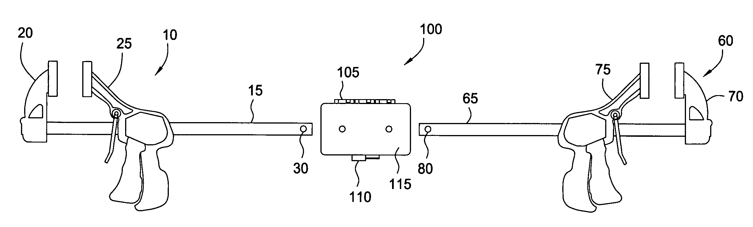
[0017]The present invention is generally directed to a coupling for quick action bar clamps. Various terms as used herein are defined below. To the extent a term used in a claim is not defined below, it should be given the broadest definition persons in the pertinent art have given that term, as reflected in printed publications and issued patents. In the description that follows, like parts are marked throughout the specification and drawings with the same reference numerals. The drawings may be, but are not necessarily, to scale and the proportions of certain parts have been exaggerated to better illustrate details and features described below. One of normal skill in the art of clamps will appreciate that the various embodiments of the invention can and may be used in all types of clamps.

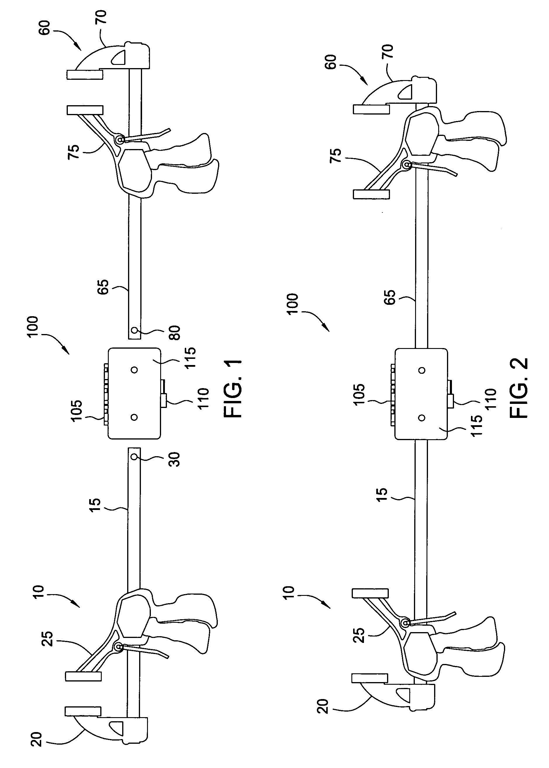
[0018]FIG. 1 is a view illustrating a coupling member 100 of the present invention with a first bar clamp 10 and a second bar clamp 60. Generally, the coupling member 100 is used to couple or conn...


PUM

PropertyMeasurementUnit
lengthsaaaaaaaaaa
sizeaaaaaaaaaa
lengthaaaaaaaaaa

Abstract

An apparatus for use in coupling a pair of bar clamps comprises a coupling member for connecting a first clamp to a second clamp is provided. The coupling member includes a first member and a second member having an end pivotally attached to the first member. The coupling member further includes a connection member for attaching an end of each clamp to the coupling member. In another aspect, a connection member for coupling a pair of bar clamps is provided. In another aspect, a method of connecting a first bar clamp to a second bar clamp is provided.

Description

BACKGROUND OF THE INVENTION[0001]1. Field of the Invention[0002]Embodiments of the present invention generally relate to clamps. More particularly, the invention relates to bar clamps. Still more particularly, the invention relates to a coupling configured to connect a pair of bar clamps.[0003]2. Description of the Related Art[0004]Traditional bar clamps are well known in the tool industry for temporarily clamping two workpieces together in order to perform an operation on one or both of the workpieces such as a gluing operation. In recent years, a quick action bar clamp has been introduced to the tool industry. The quick action bar clamp generally includes several clamp components such as a fixed jaw, a slide bar, and a movable jaw. The moveable jaw includes a trigger handle grip assembly for releasably engaging the slide bar to allow the movable jaw to easily move on the slide bar relative to the fixed jaw.[0005]Typically, the components of the quick action bar clamp are sold in a...

Claims


Application Information

Patent Timeline
Patent Type & Authority Patents(United States)
IPC IPC(8): B25B1/02
CPCB25B5/068B25B5/166Y10T403/5741Y10T403/5766Y10T403/69Y10T29/49904Y10T403/551Y10T29/49826Y10T403/553Y10T29/49716Y10T29/49815
Inventor HUBBARD, MICHAEL
Owner HUBBARD MICHAEL
Why Eureka
Try Eureka