Container with adjustable rotary lock

a technology of rotating lock and container, which is applied in the field of containers with integrated locking systems, can solve the problems of reducing the consistency of operation and a small mismatch of components, and achieves the effect of reducing the consistency of operation and reducing the mismatch of components

Active Publication Date: 2008-08-26
APEX BRANDS
View PDF18 Cites 52 Cited by
  • Summary
  • Abstract
  • Description
  • Claims
  • Application Information

AI Technical Summary

Benefits of technology

[0009]As a third aspect, embodiments of the present invention are directed to a container comprising: a receptacle having walls, a floor, and an open end; a cover pivotally attached to one of the side walls of the receptacle, the cover being movable between an open position, in which the open end of the receptacle can be accessed, and a closed position, in which the cover overlies the open end of the receptacle; a locking pin assembly fixed to the cover or one of the receptacle walls; and at least one locking system for maintaining the cover in the closed position. The locking pin assembly comprises: a mounting bracket fixed to the cover or one of the receptacle walls; a striker plate mounted to the mounting bracket and movable relative thereto; and a locking pin attached to the striker plate. The locking system comprises: a release member attached to one of the receptacle side walls; a connecting member attached to the release member; and a rotary unit including a base plate having a slot, a rotary member rotatably mounted with the base plate about a first axis of rotation, the rotary member including at least two fingers and an engagement portion, and a pawl member pivotally mounted with the base plate about a second axis of rotation and coupled with the connecting member. When the cover is in the closed position, the locking pin is received within the slot of the rotary unit base plate and engages one of the fingers of the rotary member, and the pawl member engages the engagement portion to prevent rotation thereof. Actuation of the release member disengages the pawl member from the engagement portion, thereby enabling the rotary member to rotate relative to the base plate, which rotation disengages the locking pin from the rotary member and enables the cover to move to the open position. This configuration can enable the position of the locking pin to shift relative to the slot in order to accommodate slightly misaligned cover and receptacle components.
[0010]As a fourth aspect, embodiments of the present invention are directed to a container, comprising: a receptacle having side walls, a floor, and an open end; a cover pivotally attached to one of the side walls of the receptacle, the cover being movable between an open position, in which the open end of the receptacle can be accessed, and a closed position, in which the cover overlies the open end of the receptacle; a locking pin assembly fixed to the cover; and at least one rotary unit. The locking pin assembly comprises: a mounting bracket fixed to the cover, the mounting bracket having an oblong aperture; a slide plate residing within the aperture and slidable relative thereto, the slide plate including an opening; and a locking pin inserted in the slide plate opening. The locking system comprises: a release member attached to one of the receptacle side walls; a connecting member attached to the release member; and a rotary unit including a base plate having a slot, a rotary member rotatably mounted with the base plate about a first axis of rotation, the rotary member including at least two fingers and an engagement portion, and a pawl member pivotally mounted with the base plate about a second axis of rotation and coupled with the connecting member. When the cover is in the closed position, the locking pin is received within the slot of the rotary unit base plate and engages one of the fingers of the rotary member, and the pawl member engages the engagement portion to prevent rotation thereof. Actuation of the release member disengages the pawl member from the engagement portion, thereby enabling the rotary member to rotate relative to the base plate, which rotation disengages the locking pin from the rotary member. The configuration of the locking pin assembly can also assist in locking the container when the cover and receptacle are somewhat misaligned.

Problems solved by technology

This can be problematic due to varying manufacturing tolerances (typically a truck box is the full width of a pick-up truck bed, so a slight mismatch of components can become greatly exaggerated over the full length of the truck box), or if the lid becomes slightly misshapen due to abuse, racking, or the like.
Also, the use of springs for both the engagement member and the pawl member can reduce consistency of operation, particularly when two internal lock units are used and the pins engage the engagement member at slightly different times.

Method used


Image

  • Container with adjustable rotary lock
  • Container with adjustable rotary lock
  • Container with adjustable rotary lock

Examples


Embodiment Construction

[0026]The present invention will now be described more fully hereinafter, in which preferred embodiments of the invention are shown. This invention may, however, be embodied in different forms and should not be construed as limited to the embodiments set forth herein. Rather, these embodiments are provided so that this disclosure will be thorough and complete, and will fully convey the scope of the invention to those skilled in the art. In the drawings, like numbers refer to like elements throughout. Thicknesses and dimensions of some components may be exaggerated for clarity. It will be understood that when an element is referred to as being “attached”, “connected” or “coupled” to another element, it can be directly connected or coupled to the other element or intervening elements may be present. In contrast, when an element is referred to as being “directly connected” or “directly coupled” to another element, there are no intervening elements present.

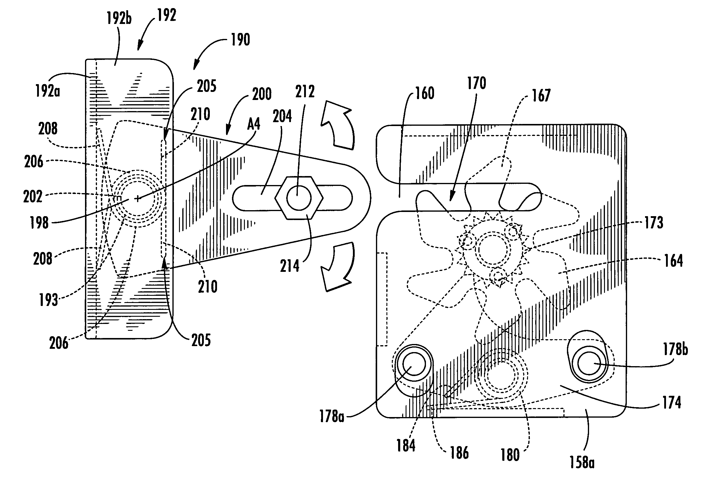
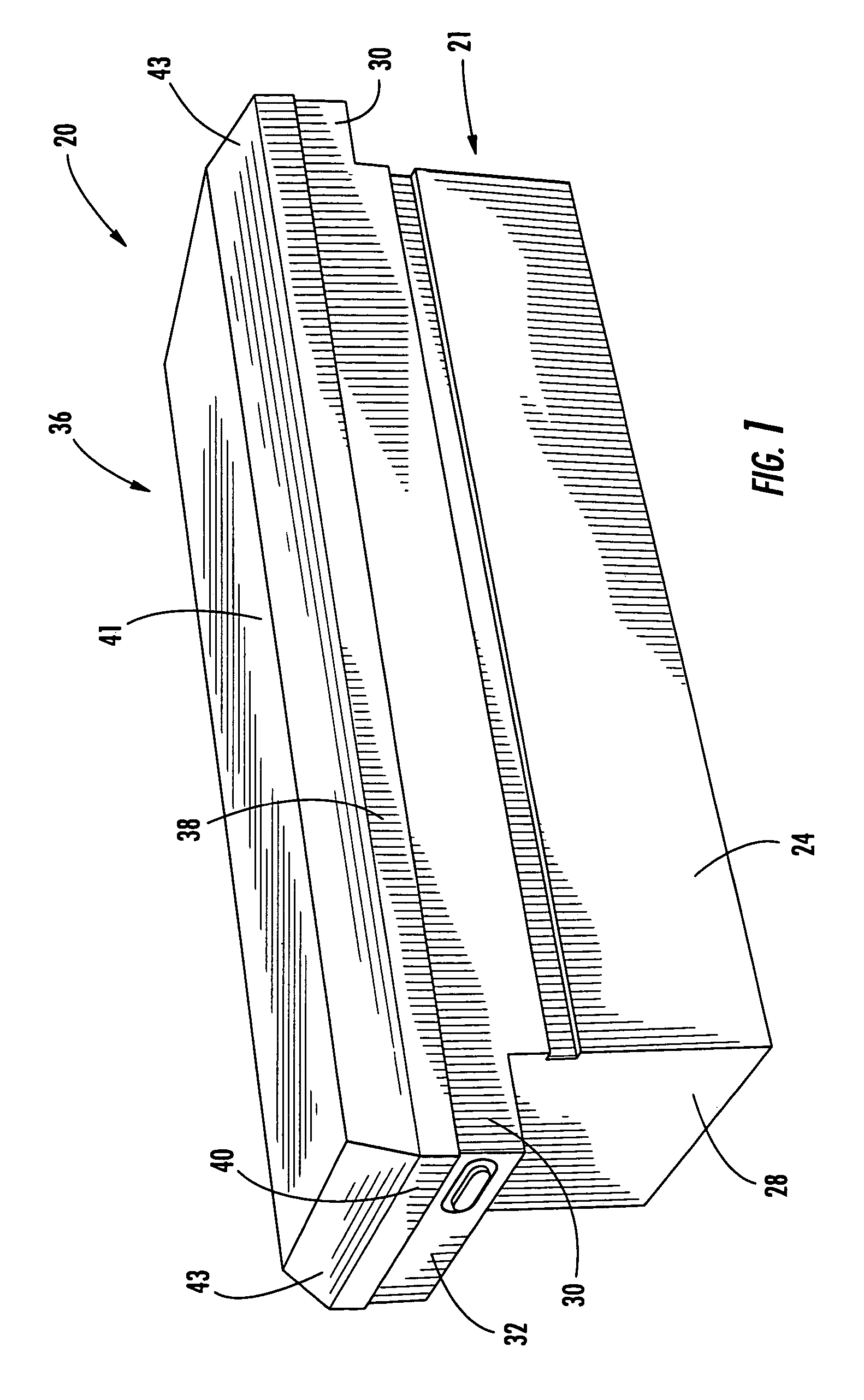
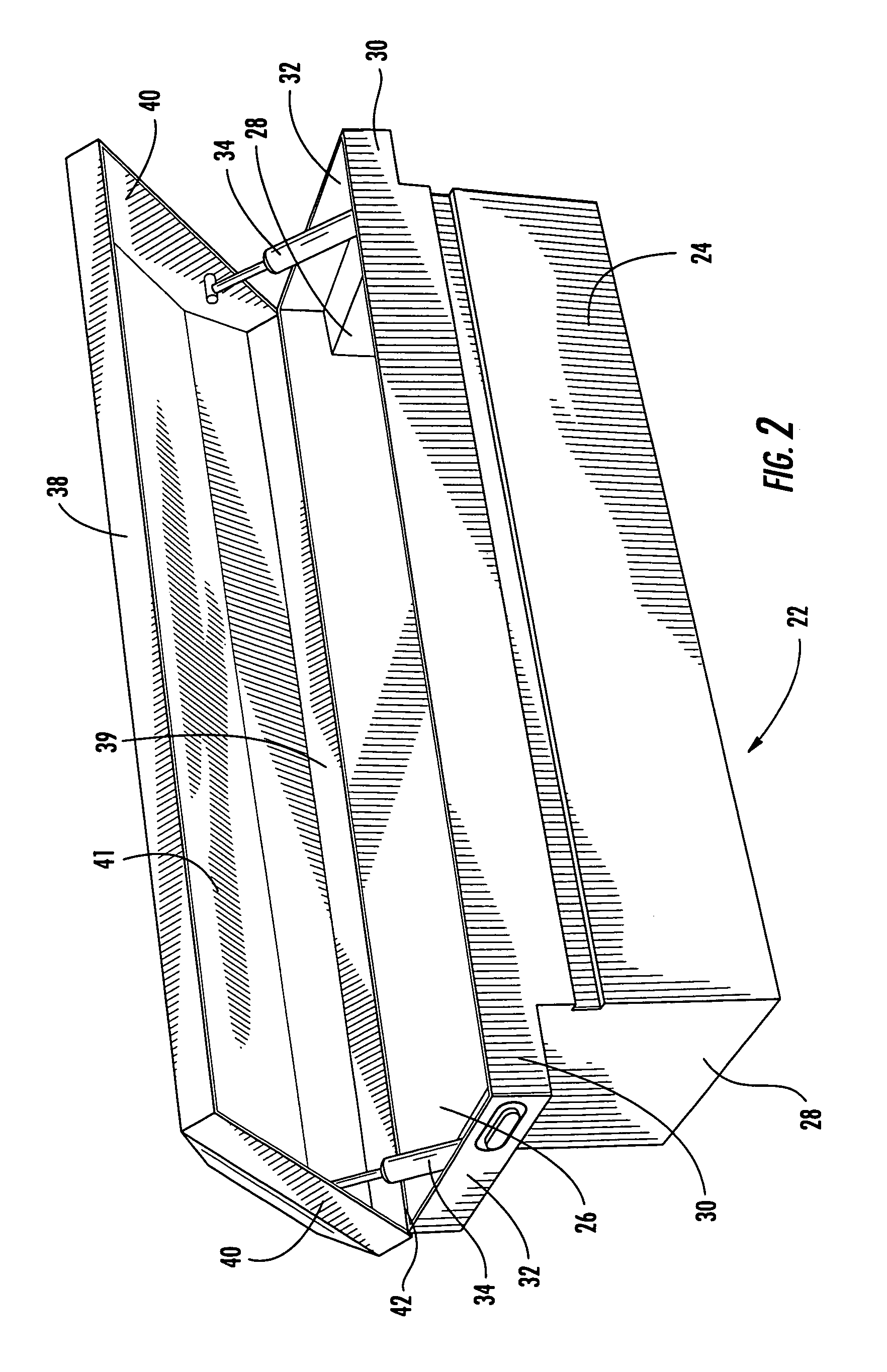
[0027]Referring now to the fig...


PUM


Abstract

A rotary unit for use with a locking system includes: a base plate having a slot; a rotary member rotatably mounted with the base plate about a first axis of rotation, the rotary member including a plurality of fingers extending radially outwardly from a central portion thereof and an engagement portion fixed to the central portion; and a pawl member pivotally mounted with the base plate about a second axis of rotation and coupled with the connecting member. The pawl member includes an engagement projection that selectively engages the engagement portion of the rotary member to prevent rotation of the rotary member in a first rotative direction but permits rotation of the rotary member in a second rotative direction that is opposite the first rotative direction.

Description

RELATED APPLICATION[0001]This application claims priority from U.S. Provisional Patent Application No. 60 / 501,212, filed 8 Sep. 2003, entitled “Container with Adjustable Rotary Lock.”FIELD OF THE INVENTION[0002]The present invention is directed generally to containers, and more specifically to containers with integrated locking systems.BACKGROUND OF THE INVENTION[0003]A truck box is a container that is mounted in the bed of a truck, typically a pick-up truck. Ordinarily, the truck box is mounted directly behind the cab of the truck and spans the distance between the side walls of the truck bed. Items like tools, fasteners, and the like can be stored in the truck box rather than simply laying loose in the truck bed.[0004]A typical truck box has a rectangular receptacle and a lid that opens to permit access to the interior of the truck box. Many truck boxes have lateral portions, termed “tray pockets,” that overlie the walls of the truck bed to provide additional storage space. In som...

Claims


Application Information

Patent Timeline
Patent Type & Authority Patents(United States)
IPC IPC(8): E05C3/06E05C3/16E05B15/00E05B15/02E05B53/00E05C3/24
CPCE05B15/0046E05C3/24E05B53/00E05B15/024Y10S292/24Y10T292/1045Y10T292/1047Y10T292/705
Inventor PFITZINGER, KURTANDERSON, BRYANJONES, KELLYEBERWEIN, RONKEY, RANDY
Owner APEX BRANDS
Why Eureka
Try Eureka