Automatic flow shut-off system

Inactive Publication Date: 2008-09-16
MARTIN JAMES B +1
View PDF13 Cites 38 Cited by
  • Summary
  • Abstract
  • Description
  • Claims
  • Application Information

AI Technical Summary

Benefits of technology

[0012]One end of the arm is biased downward and rests on a plunger in the housing which, in turn, is prevented from moving downward by a water reactive material, e.g. paper towel material. W

Problems solved by technology

When a leak or the like develops around the appliance, water will

Method used


Image

  • Automatic flow shut-off system
  • Automatic flow shut-off system
  • Automatic flow shut-off system

Examples


Embodiment Construction

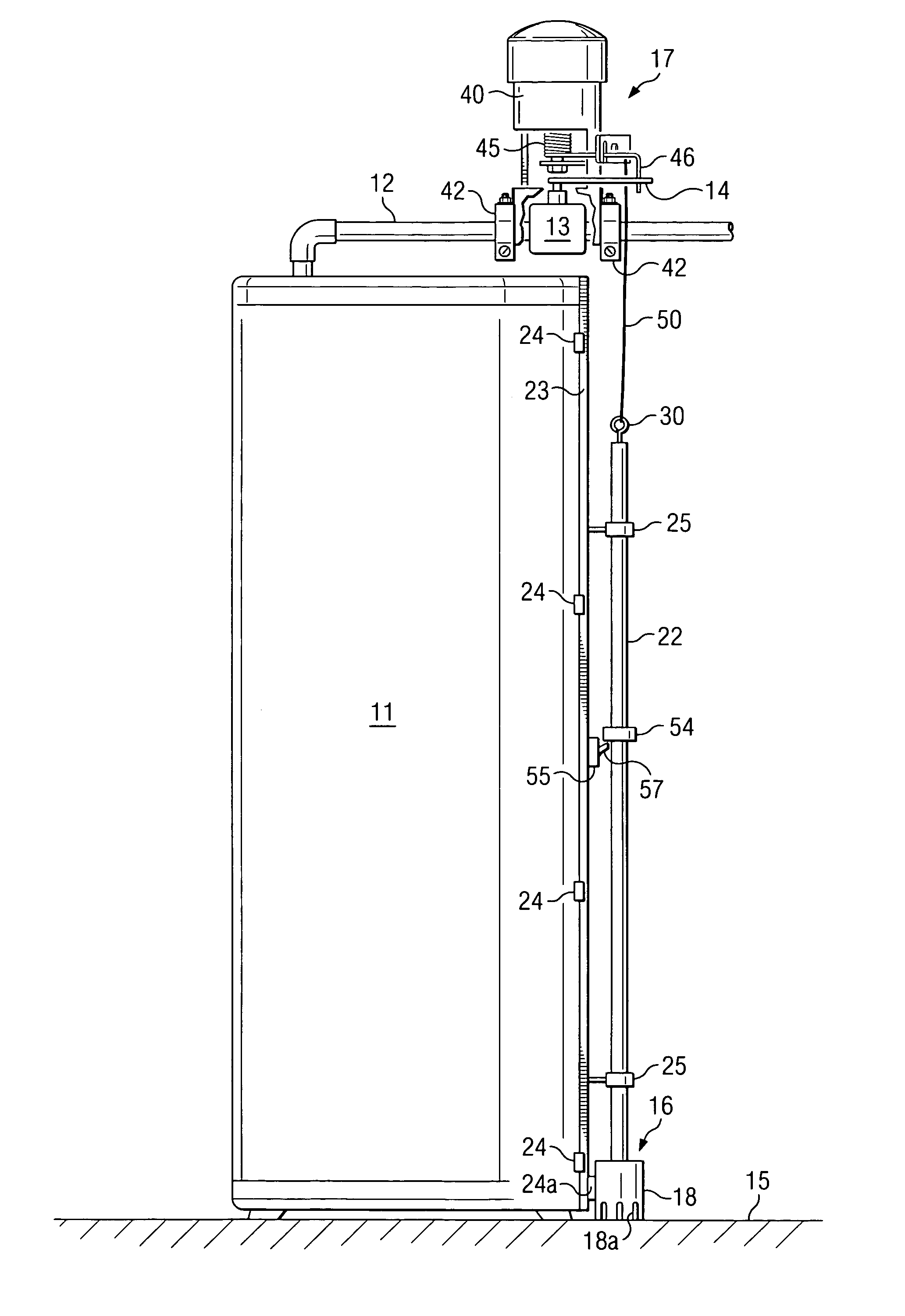
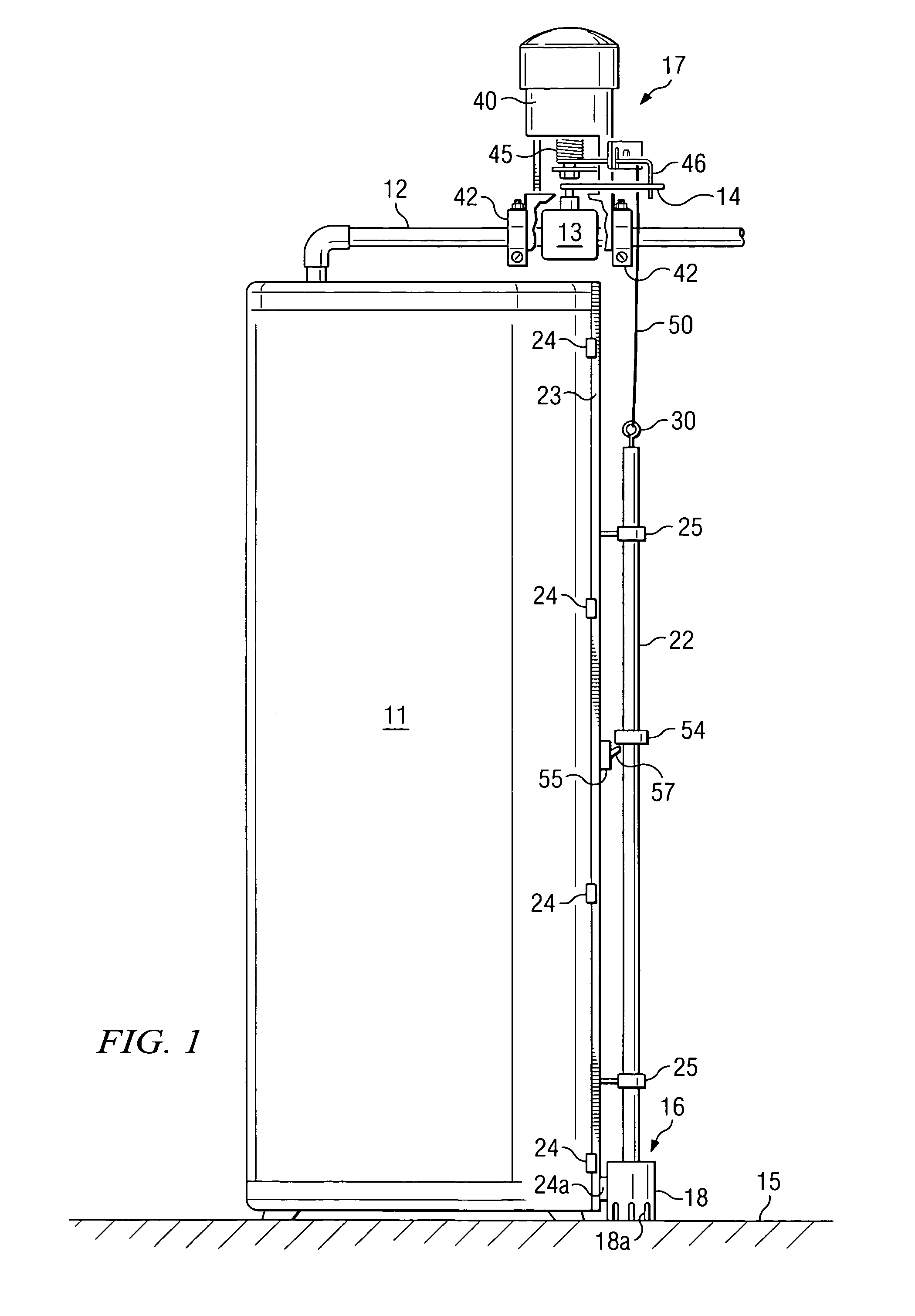
[0028]Referring more particularly to the drawings, FIG. 1 illustrates the automatic flow shut-off system 10 of the present invention when used with a typical hot water heater 11. Water heater 11 is positioned on a substantially horizontal floor 15 and has a water supply line 12 connected thereto. It should be understood that shut-off system 10 can be installed at the time of the original installation of a water heater or the system may be bought as a kit and installed into already installed hot water heaters. Again, it is pointed out that it is not necessary for the hot water heater to be positioned in a pan or the like for the present invention to function as is the case with several prior art devices.

[0029]Typically, the existing plumbing for many installed water heaters include a standard type ball valve 13 for controlling the flow of water through line 12 and such a standard ball valve can easily be installed if required. As will be understood in the art, ball valve 13 remains o...


PUM


Abstract

An automatic system which includes a tripper unit for actuating a device (e.g. valve-closing actuator) upon contact with water. Basically, the tripper unit is comprised of a housing having a cartridge therein which, in turn, is wrapped with an adsorbent paper which prevents a plunger from moving downward. When a leak occurs, water will flow into the housing and into contact with the absorbent paper which will quickly disintegrate allowing the plunger to move downward to thereby actuate the valve actuator to close the valve. The tripper unit may be a separate component of the system or both the tripper unit and the valve actuator can be incorporated into a single unit.

Description

TECHNICAL FIELD[0001]The present invention relates to an automatic flow shut-off system and more particularly relates to a system for automatically shutting off the water and / or gas supply to an appliance (e.g. hot water heater, commode, washer, etc.) when the appliance ruptures or springs a leak.BACKGROUND OF THE INVENTION[0002]Almost everyone is familiar with the problems caused by unexpected leaks or overflows in household or commercial appliances such as hot water heaters, commodes, and the like. For example, if the tank of a hot water heater cracks or springs a leak which goes undetected for any period of time, the results can be economically devastating. That is, water will continuously flow into the leaking tank and out onto the floor until the leak is detected and the water is cut off. If the owner is away on vacation or does not promptly become aware of the leak or rupture, the premises quickly floods which, in turn, can cause extensive damage to the affected floors, rugs, ...

Claims


Application Information

Patent Timeline
IPC IPC(8): F16K13/08F16K17/36
CPCF16K31/001Y10T137/5762Y10T137/1624Y10T137/1632
Inventor MARTIN, JAMES B.JONES, LLOYD G.
Owner MARTIN JAMES B
Why Eureka
Try Eureka