
Whistle

a signaling device and whistle technology, applied in the field of whistles, can solve the problems of traditional whistles, damage to user's ear drums, damage to user's ear drums, etc., and achieve the effects of less sound waves, less damage to user's eardrums, and larger air tunnels

Active Publication Date: 2008-09-30
KIM KEUN JUNG
View PDF28 Cites 11 Cited by
  • Summary
  • Abstract
  • Description
  • Claims
  • Application Information

AI Technical Summary

Benefits of technology

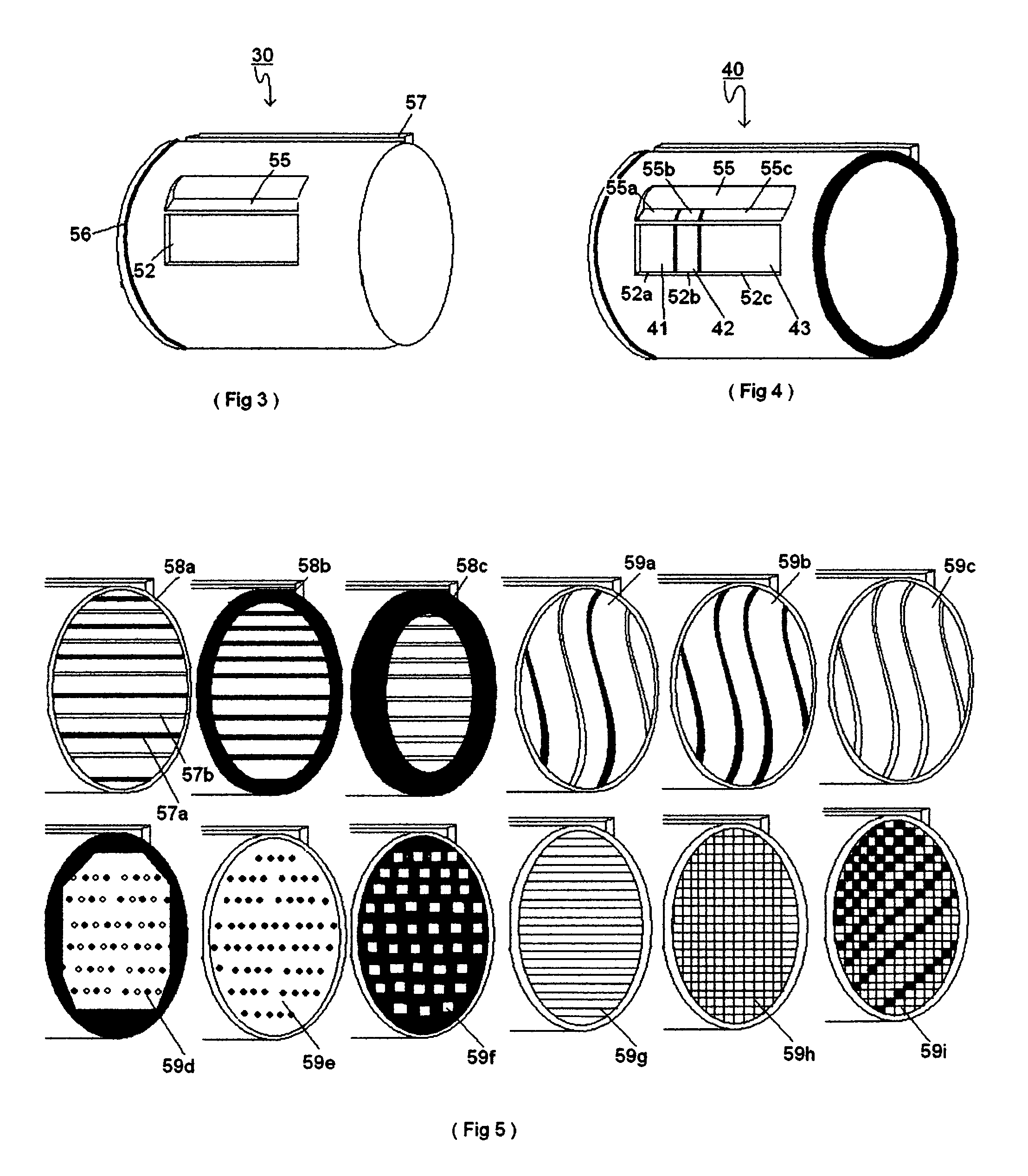
"The present invention is a whistle device that solves problems by placing the sound outlet on the front of the whistle, allowing the sound to be sent forward motion towards the intended subject. The device also uses sound reflectors and angled air tunnel to redirect the sound waves forward, reducing harmful effects on the user's ear drums. The shape of the sound chamber inside the whistle can change the tone and pitch of the sound, and the device allows users to customize the sound by picking different lay out of the sound chamber. The concave shape of the whistle device provides a larger air tunnel and a firm grip. The invention allows for faster turning of the ball and vibration of the ball vigorously to make more sound waves, resulting in different tone of sound that will be sent out at the front of the whistle device."

Problems solved by technology

The deficiency of traditional whistle is that whistle have sound opening at the top or topside of the whistle.
Which will damage the user's ear drums.
Still the air going through the sound chamber is the same amount due to narrow air tunnel of the whistle and sound opening at top of the whistle which will damage user's ear drums.
U.S. Pat. No. 3,824,949 issued to Christopher J. Aquila had good idea using megaphone to direct the sound but it is not convenient to use the system due to long air tube and chain to attach tube to a user also need clip for attachment to the belt of waistband of the user.

Method used


Image

  • Whistle
  • Whistle
  • Whistle

Examples


Embodiment Construction

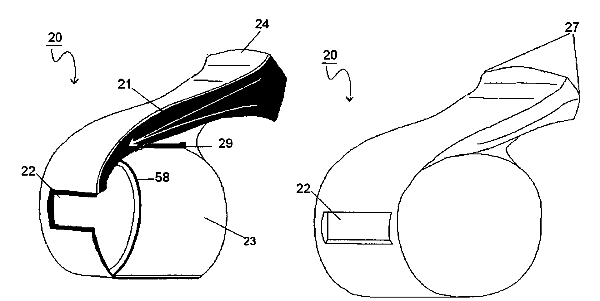
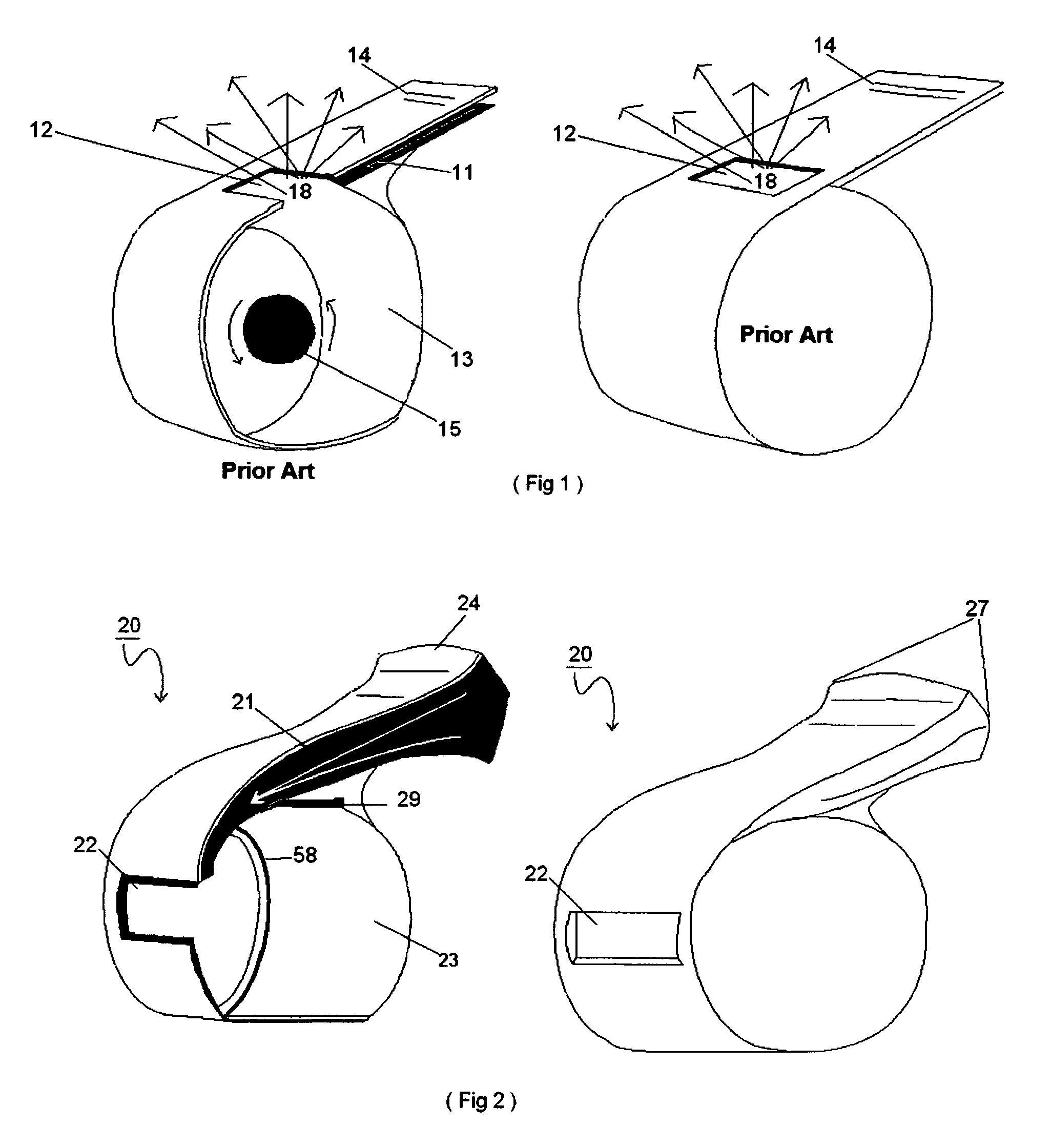
[0026]It clearly show on FIG. 1. A traditional whistle with narrow air inlet tunnel 11 where user blow air into a whistle to make cork pea or ball 15 to bounce around the smooth surface of whistle's sound chamber 13 to make sound warble. After ward forced by the air in the sound chamber, sound waves 18 is pushed out to sound outlet 12 which is located top of the whistle. Where whistle device emit an audible sound signal to alert the intended subject. FIG. 1 also shows flat area of whistle mouth peace area 14. On FIG. 2 shows new whistle device 20 with elongated wide open mouth portion 24 with larger air tunnel 21 with where user's mouth portion area 24 have been curbed up and downward also left and right to fit mouth securely when user blow hard into the air tunnel 21. This way whistle device will not be blown out of the user's mouth also by having sound outlet first opening 22 in front of the whistle, sound will go forward. It also shows guide groove 29 at its inner side and lockin...


PUM


Abstract

A new whistle which emits louder sound level with easiness of blowing air through the whistle. It direct the sound to intended subject by having sound opening area in front of the whistle to direct sound waves to go forward motion and it has capacity to change the insert able wound chamber and insert able sound chambers are attach able to each others. Also using a sound reflector and angled air tunnel on whistle with opening on top can be used to make sound waves go forward.

Description

CROSS-REFERENCE TO RELATED APPLICATIONS[0001](not applicable )STATEMENT REGARDING FEDERALY SPONSORED RESEARCH OR DEVELOPMENT[0002](not applicable )REFERENCE TO SEQUENTIAL LISTING, A TABLE, OR A COMPUTER PROGRAM LISTING APPENDIX SUBMITTED ON A COMPACT DISC[0003](not applicable )BACKGROUND OF THE INVENTION[0004]1) Field of the Invention[0005]This invention relates to a whistle or signaling device which produce louder sound to the subject it trying to reach with interchangeable sound chamber which has all different types of tone and multi tone of user's choosing. Also it reduces sound level to the user's ear drum. This whistle's mouth piece is shaped in such way it is comfortable but stay firmly in the mouth. By shape, it allow larger volumes of air into the interchangeable sound chamber. Also using attachments on existing whistle to make the sound waves go forward.[0006]2) Description of the Related Art[0007]It is known to use a mouth blown device so call whistle to guide traffic or s...

Claims


Application Information

Patent Timeline
Patent Type & Authority Patents(United States)
IPC IPC(8): G10K5/00
CPCG10K5/00
Inventor KIM, KEUN JUNG
Owner KIM KEUN JUNG
Learn More