Bar knob with cam-operated locking mechanism

a locking mechanism and bar knob technology, applied in band saws, metal sawing accessories, manufacturing tools, etc., can solve the problems of elongation of the chain, loosening of the cutting chain of the chain saw, etc., and achieve the effect of adjusting the tension of the cutting chain and preventing accidental loosening

Inactive Publication Date: 2008-10-14
HUSQVARNA OUTDOOR PROD INC
View PDF22 Cites 39 Cited by
  • Summary
  • Abstract
  • Description
  • Claims
  • Application Information

AI Technical Summary

Benefits of technology

[0051]The present invention can provide various advantages. For example, the present invention can enable an operator to make adjustments to the guide bar without additional tools. Additionally, the present invention provides for a positive securing of the knob against unwanted rotational movement while allowing for the ready release of the knob when rotational movement is desired.

Problems solved by technology

The cutting chain of a chain saw, eventually, will become loose on the chain saw's guide bar after use because of factors, such as wear, that result in elongation of the chain.

Method used


Image

  • Bar knob with cam-operated locking mechanism
  • Bar knob with cam-operated locking mechanism
  • Bar knob with cam-operated locking mechanism

Examples


Embodiment Construction

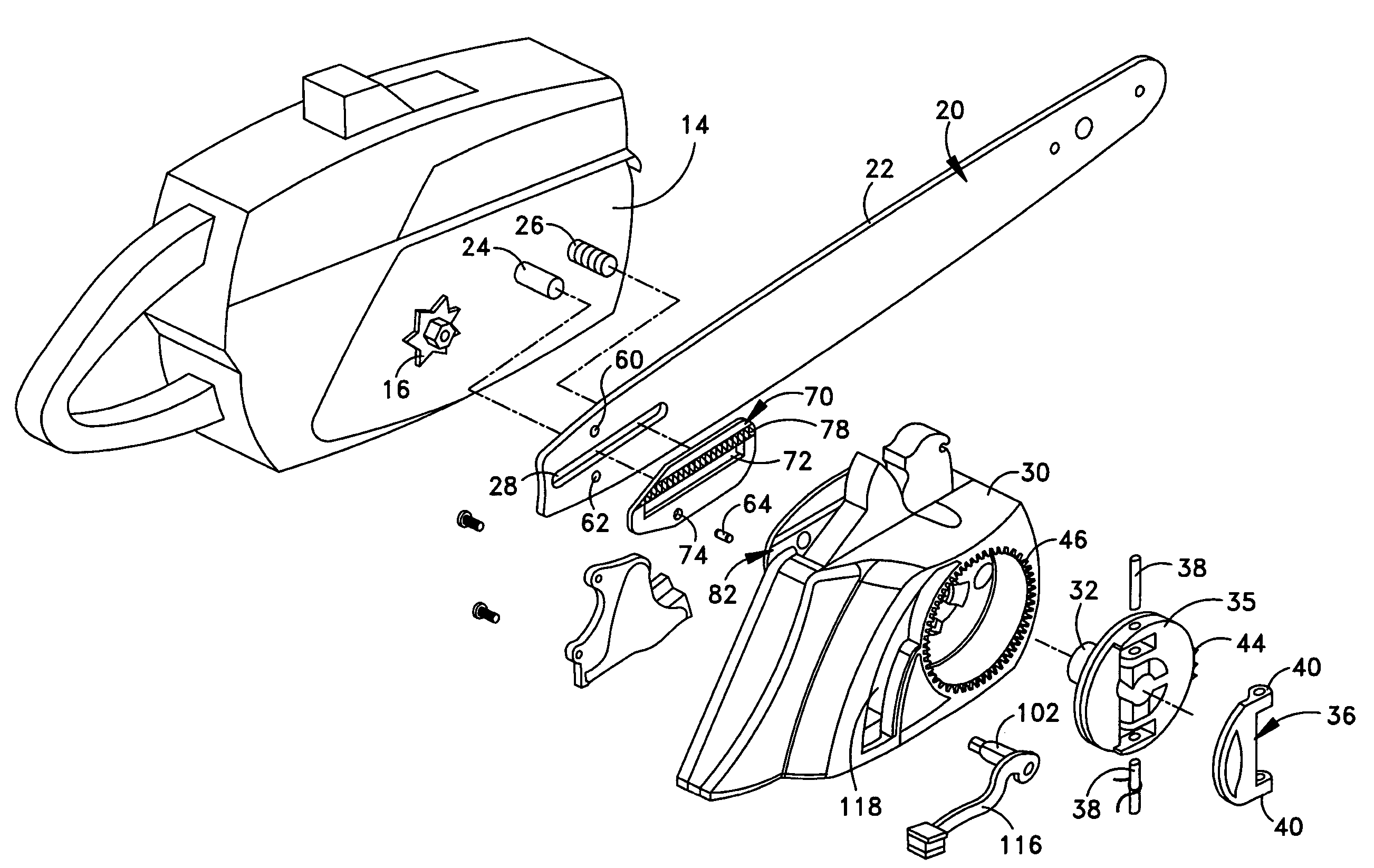
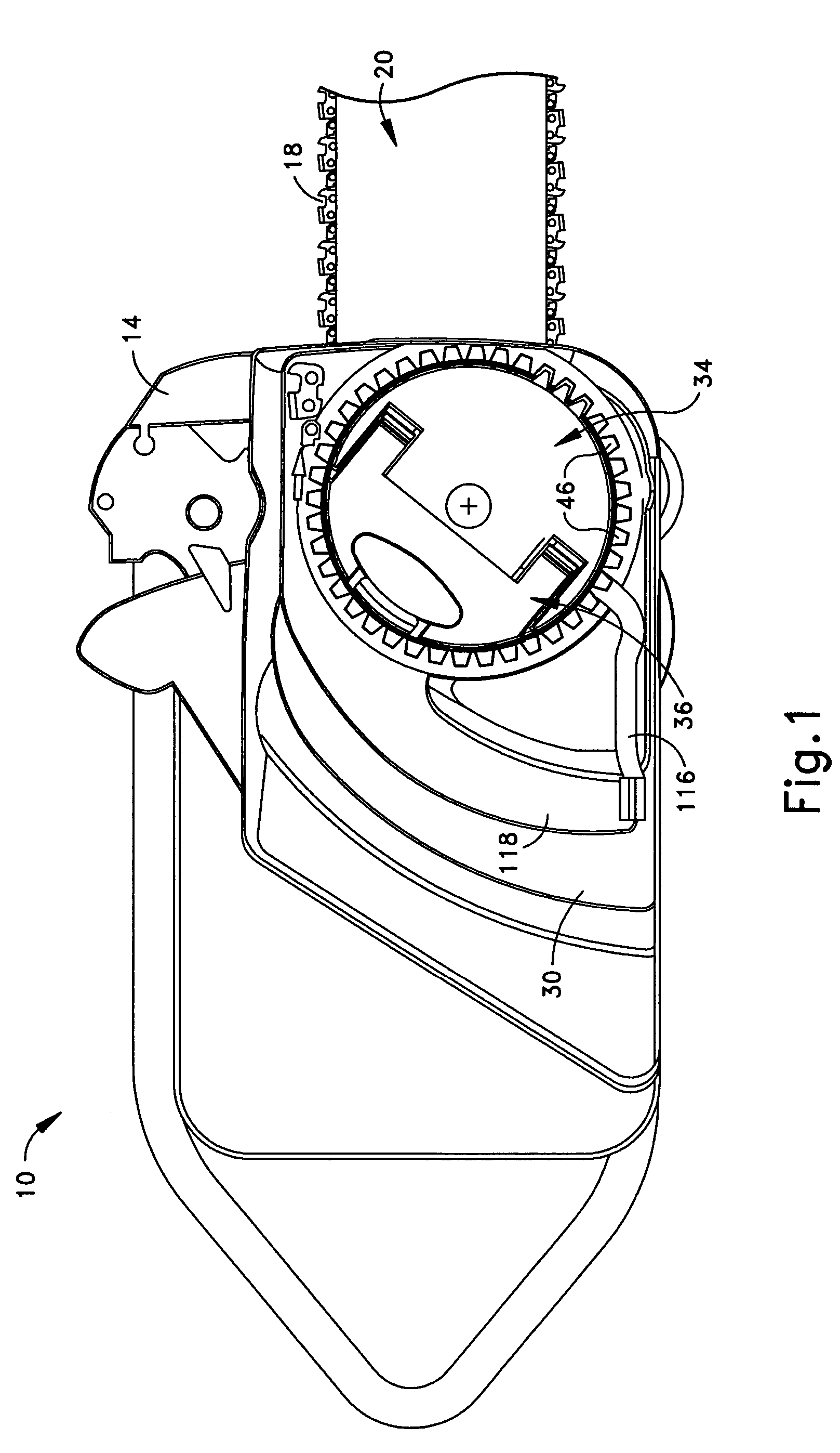
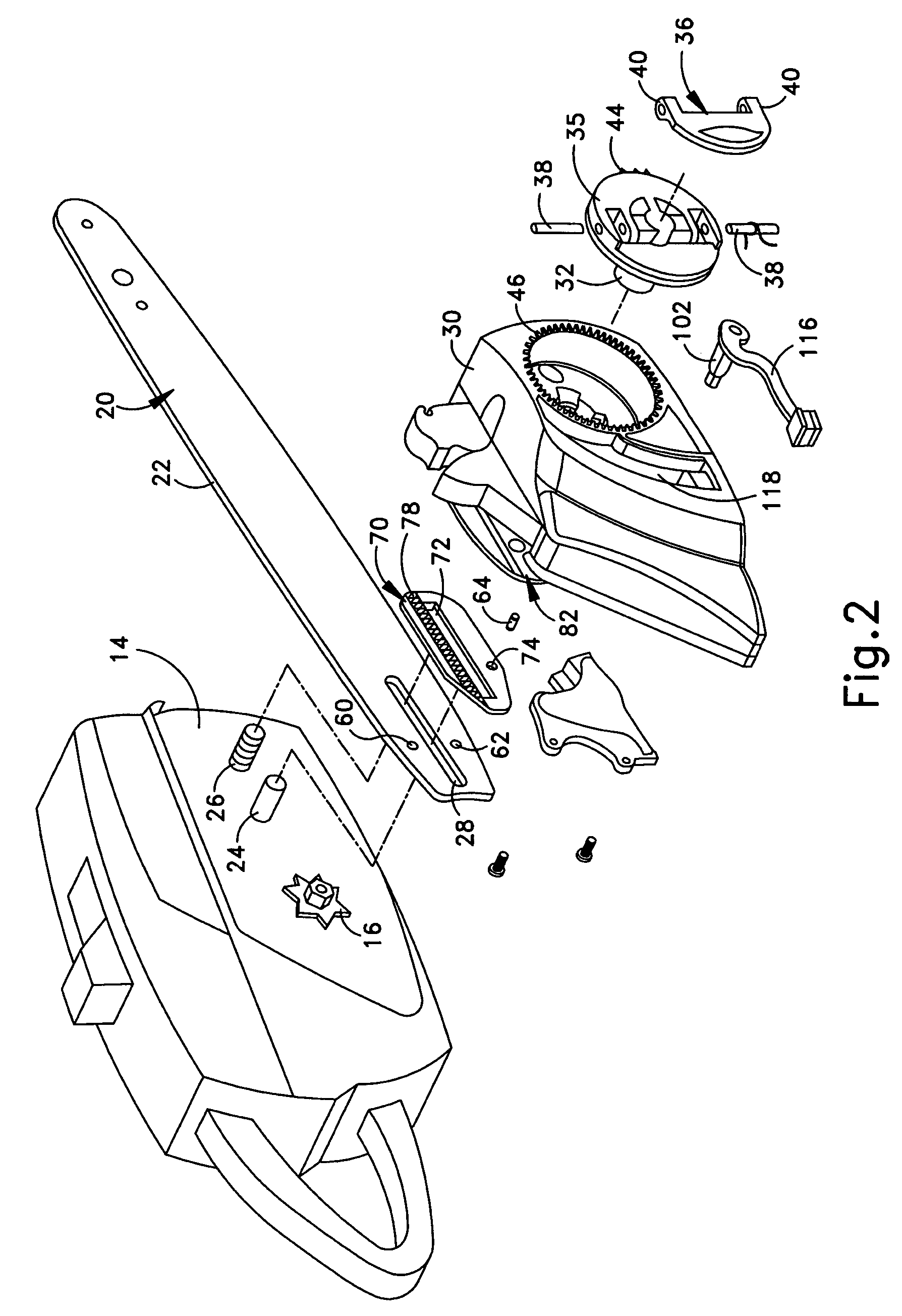
[0025]FIGS. 1 and 2 illustrate a chain saw 10 that includes an example of a retaining assembly 34 (FIG. 1) for a tensioning arrangement for adjusting the tension of the chain saw's endless cutting chain 18 (FIG. 1) in accordance with the present invention. The chain saw 10 includes an engine chassis 14 for an engine (not shown), a clutch cover 30 and a guide bar 20 for the cutting chain 18. As will be understood, the engine powers a drive sprocket 16 (FIG. 2) attached to the drive shaft of the engine. The drive sprocket 16 engages the links of the cutting chain 18 and propels the cutting chain around the guide bar 20 (FIG. 1).

[0026]The guide bar 20 has the configuration of an elongated plate with a channel or groove 22 (FIG. 2) around its periphery and an idler sprocket (not shown) at its distal end in which the links of the cutting chain 18 ride. Parallel pins, or studs, 24 and 26 are affixed to the chassis 14 and lie in a common plane that is, generally, horizontally arranged when...


PUM

PropertyMeasurementUnit
tensionaaaaaaaaaa
elongationaaaaaaaaaa
lengthaaaaaaaaaa

Abstract

A chain saw includes a retaining assembly for a tensioning arrangement for adjusting the tension of the cutting chain in the chain saw. The retaining assembly includes a rotatable knob for operation with the chain saw's engine chassis, clutch cover, and guide bar and is rotatable about an axis of rotation between a tightening position for holding the guide bar in place and a loosening position enabling the guide bar to be repositioned whereby the tension in the cutting chain is adjusted. A locking mechanism is provided for locking and unlocking the knob. When the locking mechanism is in a locking position, moveable engagement points of the locking mechanism extended beyond the confines of the knob and engage fixed engagement points. When the locking mechanism is in the unlocking position, the moveable engagement points, having moved inwardly of the confines of the knob, are disengaged from the fixed engagement points.

Description

FIELD OF THE INVENTION[0001]The present invention relates to a retaining assembly for a tensioning arrangement for periodically adjusting the tension of an endless cutting chain on the guide bar of a chain saw.BACKGROUND OF THE INVENTION[0002]The cutting chain of a chain saw, eventually, will become loose on the chain saw's guide bar after use because of factors, such as wear, that result in elongation of the chain. Several chain saw constructions and associated methods exist to move the guide bar longitudinally away from the drive sprocket of the chain saw to remove slack from the cutting chain and apply the requisite tension to the cutting chain. This ensures that the links of the cutting chain remain snuggly seated in a peripheral channel in the guide bar.[0003]A number of tensioning arrangements and associated methods for adjusting the tension of the cutting chain on the guide bar are known. Typically, retaining assemblies are provided for the tensioning arrangements. The retain...

Claims


Application Information

Patent Timeline
Patent Type & Authority Patents(United States)
IPC IPC(8): B23D57/02
CPCB27B17/14Y10T83/7239
Inventor KEETON, WILLIAM B.WARFEL, PAUL A.
Owner HUSQVARNA OUTDOOR PROD INC
Why Eureka
Try Eureka